Forum rules
The DIY forum is for personal projects (things that are not for sale, not in production), info sharing, peer to peer assistance. No backdoor spamming (DIY posts that are actually advertisements for your business). No clones of in-production pedals. If you have concerns or questions, feel free to PM admin. Thanks so much!
I've been trying to figure out how to make this on breadboard
I get about halfway and then my eyes go crossed by the time I get to the second capacitor. I'm confused about the intersection of parts. Does it matter the order they are on a rail? This breadboarding thing is so weird to me. It's so few parts. One time I got it to what I thought was finished, but it sounded like I had a transistor in backwards, which I was too new in to realize. Since, I haven't approached the breadboarding technique. I'd like to get that Fuzz Face breadboard kit from Small Bear but can't at the moment. The circuit is similar so it may help. I tried going a long with it and translating it for the One knob schematic but eventually my confusion was too deep.
Any simpler things to approach than this simple thing circuit? Maybe if there's software where I can put a schematic in and it breadboards the circuit...is this really that complicated?! help me breadboard!
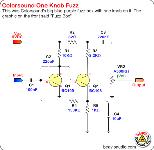
Note that it uses two 10u capacitors. You can use practically any value capacitor and get sound. The build doc suggests as low as 200 picofarads. The diode can be practically any standard diode. If you don't have one, you can pull one out of just about any electronic device that is headed for the trash. Same for the transistor-- just about any NPN transistor will work. Just check the datasheet to make sure you have the pinout right.
you can breadboard it without C2 and VR2 as a bare minimum just to see if it works. then you can add in C2. you do not need VR2 at all. just turn it down on the amp. every black dot is called a net. just like in math with multiplication and addition, the rule of commutative properties still applies. for example R2, R3, C3 are all connected at a net, we can call it N$1. that net can be any combination of wires, component leads, tin foil, or breadboard busses in any order in any place on the breadboard or even flying. you can connect R2 and R3 to the same bus and run a wire to another bus where C3 is all alone. by alone I mean alone with the exception of the wire that you just connected to C3. sometimes I scartch out my breadboard layouts on paper so the breadboard process is fast and painless while using less space.
Thanks guys, had a blast with the bazz fuss for a few hours and then wired up the one knob first try with no sweat....however, realizing that I need to ground the ground rail to something to complete the circuit took a little bit. However, I confidently assembled the circuit and that's really what I wanted, so thanks a bunch.
Using an LED for the diode in the bazz fuss is pretty choice.


")
