Forum rules
The DIY forum is for personal projects (things that are not for sale, not in production), info sharing, peer to peer assistance. No backdoor spamming (DIY posts that are actually advertisements for your business). No clones of in-production pedals. If you have concerns or questions, feel free to PM admin. Thanks so much!
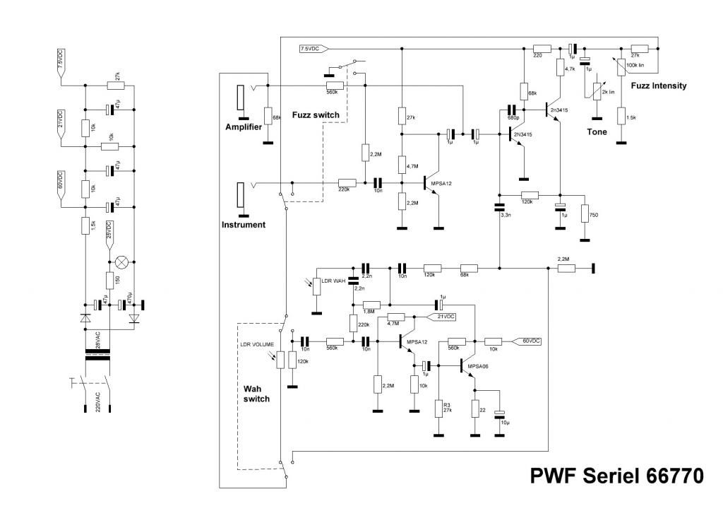
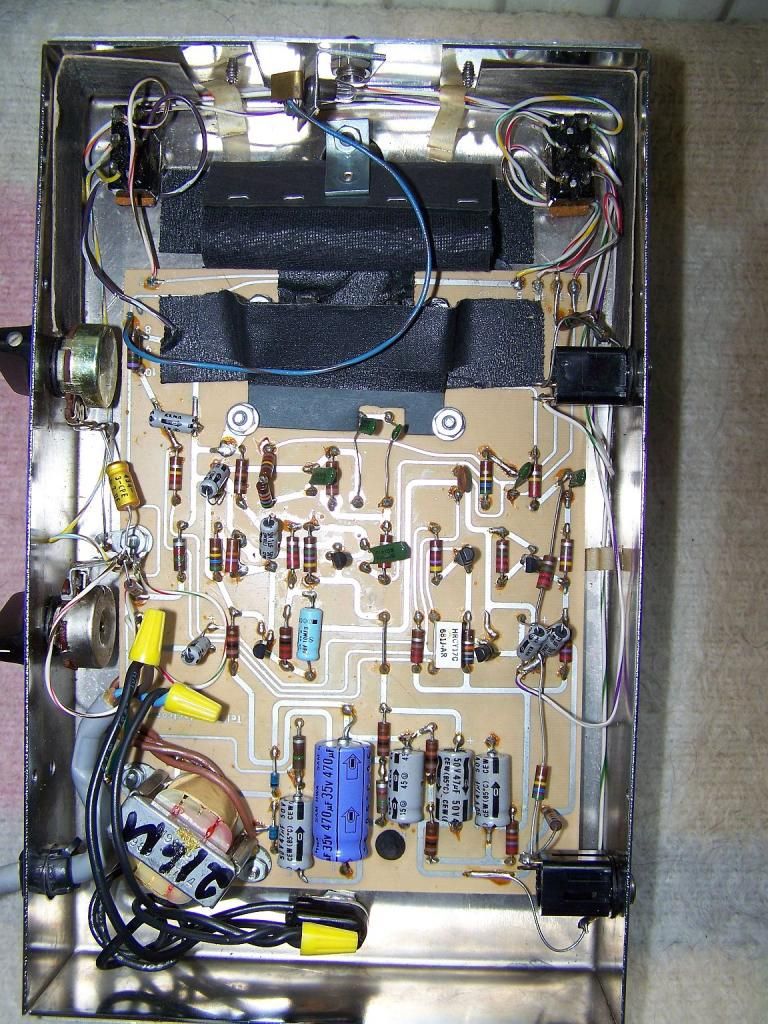
Had a few of these enormous chrome spaceship fuzz wahs in the past. Got one here that's giving out a very gated fuzz tone. My partially-educated guess is that the voltage is too low on the collector of one or more of the trannies and needs a different resistor. Not sure which trannies do the fuzzing, here's the schematic. ...
Collector voltage would be my guess, as well. I think the wah transistors are the two to the left-hand side of the board. Handy resistor color-code chart here for helping match your trace to the schematic: http://www.google.com/imgres?imgurl=htt ... Q&dur=1518
D.o.S. wrote:Broadly speaking, if we at ILF are dropping 300 bucks on a pedal it probably sounds like an SNES holocaust.
friendship wrote:death to false bleep-blop
UglyCasanova wrote:brb gonna slap my dick on my stomp boxes
collector resistor being too big is only one way to get a gated effect. another possible answer is that your BE junction is reverse biased or just close enough to BEvf of 0.7v. on Q1, the 4.7M and 2.2M create a voltage divider that biases the base of Q1. voltage dividers are pretty simple. take your supply voltage multiply it by this number R2/(R1+R2) where R1 is pulled up to V+ and R2 is pulled down to 0v. for example 2,200,000/(4,700,000+2,200,000) = 0.318840. then multiply that by 7.5v and you get 2.39v at the base. I cheated a little since I left out the 27k. in the math, R1 would really be 4,727,000. what if we had %20 resistors? lowest voltage possible at the base is 2.36v.
so yeah back to looking at the collector resistors or bad transistors. it is really old after all. I would say the power supply has a risk of flyback spikes in the 200v+ range when the power is disconnected. this is more than enough to kill even the biggest of the transistors used. that MPSA06 is rated at a max VCE of 80v, see the datasheet here http://www.fairchildsemi.com/ds/MM/MMBTA06.pdf if you are not familiar with flyback spikes that come from switching inductive loads (the power transformer), I highly suggest you look into it. http://en.wikipedia.org/wiki/Flyback_diode


