Forum rules
The DIY forum is for personal projects (things that are not for sale, not in production), info sharing, peer to peer assistance. No backdoor spamming (DIY posts that are actually advertisements for your business). No clones of in-production pedals. If you have concerns or questions, feel free to PM admin. Thanks so much!
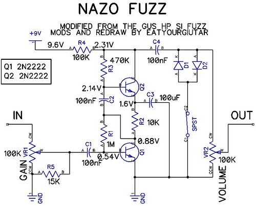
I added an RC low pass filter on the input to reduce noise. so R5 R6 C5 are all optional. without the diodes and dip switch, it is a clean boost. VR4 can be a 33k or 100k resistor. 100k is standard, 33k is really loud and not as clean. pots are off board. C3 replaces C6 depending on if you are using axial or radial electrolytic capacitor. just bend your radial cap over so it lays down flat. comments, suggestions etc.. do you see any mistakes?
Some PCB factory places have rules like "all angles have to be 45°" or something.. so I'd check the DRC before handing it in for production. Most places offer .dru files for download so you don't have to set everything up yourself. Also- why do you do normal tracks for ground? If you etch yourself it would save you a lot of money if you did ground-plates (you know with polygons and stuff)... so you would have less copper to etch off the board- meaning you could etch more boards per bath.
Schlatte wrote:Some PCB factory places have rules like "all angles have to be 45°" or something.. so I'd check the DRC before handing it in for production. Most places offer .dru files for download so you don't have to set everything up yourself. Also- why do you do normal tracks for ground? If you etch yourself it would save you a lot of money if you did ground-plates (you know with polygons and stuff)... so you would have less copper to etch off the board- meaning you could etch more boards per bath.
this is a 2 sided board, I am not etching it myself. I have checked using the DRC tool in eagle with the .DRU rules file provided by my PCB fabricator. it passes DRC. also, this company does not have requirements for angle of corners on traces.
multi_s wrote:nice work, you should usa ground plane if you are doing 2 layer though.
I'm not sure how much shielded cable, ground planes, power filtering caps etc.. we need in pedals. some circuits are fine without them. I need to go read some more on adding ground planes with eagle. maybe I will add a ground plane.
if you want to try its real easy. just draw a polygon with the polygon tool that is the same size as the pcb. make sure you set the layer of the polygon to whatever side you want the plane on (16 for example is the bottom of a 2 sided pcb.) then use the rename command to name the polygon GND or whatever your ground signal name is. hit the rats nest button and it will fill the polygon but leave space so its not touching any thing that isnt ground.
i was supposed to make a few for a local artist. , which is why it exists. there is a second pcb with 4 mic preamps and various other analog buffers for the specified design. its a redux of the quad thing with the joystick i posted a year ago or something. its to drive a dome made out of speakers so the idea was to play a lot with spatialization of sound, short echos, microphone feedback, etc. i dont have any real plans to go into production on it but there will more than likely be pcbs left from the run after the project.


 .
.