Forum rules
The DIY forum is for personal projects (things that are not for sale, not in production), info sharing, peer to peer assistance. No backdoor spamming (DIY posts that are actually advertisements for your business). No clones of in-production pedals. If you have concerns or questions, feel free to PM admin. Thanks so much!
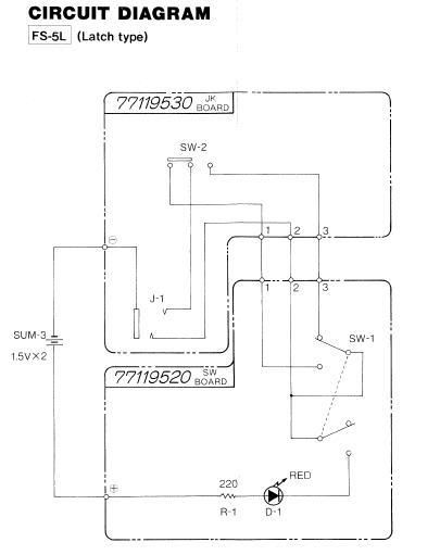
So I'm needing to make one of these suckers, but can't read schematics. I know right? It seems as simple as most bypass loopers though. Maybe not, I dunno. Can anyone help me find a wiring diagram that shows the 3dpt switch, input and output jack...etc. This is what I've been able to find through Diystompboxes. Again, don't understand schematics. I get some of it, but not all of it.
I'm looking for something like this
"I do not have the ability to think rationally 90% of the time and I also change my mind at the drop of a hat".
Can anybody help me add a two color led to this? My LED has a center common negative and two + wires for red and green status.
I built my FS5L in a 1590a enclosure and am using it to switch between modes in my Boss SD-2, but would like to always see which mode is on when the pedal is off [red/green]
Like the OP, I cant read schematics ...
I cant for the life of me figure out how an led with 2 positive legs [which both need to connect to the + DC jack with individual current limiting resistors] and only one negative leg for the footswitch can be wired to this circuit?
Outstanding!
So, both + legs to the footswitch without current limiting leds and the middle f/s lug has the CRL.
How does the mini polarity switch factor in now?


 I know right? It seems as simple as most bypass loopers though. Maybe not, I dunno. Can anyone help me find a wiring diagram that shows the 3dpt switch, input and output jack...etc. This is what I've been able to find through Diystompboxes. Again, don't understand schematics. I get some of it, but not all of it.