
rfurtkamp wrote:I just call it the Test Pattern from Hell, it fits.
viewtopic.php?f=149&t=46055&p=935562#p932184rfurtkamp wrote:Relevant to your interests with the blessings of the guy who did it for me:
He says:
"To get 'closer' to the original test pattern version of crazy, putting the 'high gain' versions of the active components and also lowering the R1 value will put it back squarely in the original TP area." Or removing R1 completely if you want maximum insanity.
Go with higher-gain versions of things as well to get more silliness/uncontrollable stuff if you so desire as well.
Effectively, this version is a "more refined" and controllable (not saying much) Test Pattern with a hybrid of design choices from the various Devi circuits - if I recall, it's the originalish Soda Meiser versus the last (then) revised that's in the stock one, with noise and chaos switches plus the normal bypass half the circuit one, and add a starve.
Have a PDF of a brew your own PCB as well if anyone needs it.
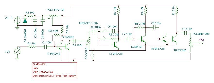
i compared rfurtkamp's posted (godboxfx modified) 'test pattern from hell' with the known reliable devi ever schemos for the original sm (soda meiser) and 33 silver crank (33) along with the original devi ever test pattern off board sm+33 linking layout, and thought it might be of interest to members here if i posted my findings and conclusions re building your own mutant 'test pattern from hell' according to the variations/mods between the two.
(note: have declined from posting the referenced original devi schemos in this thread but you know where they are if you want to reference them. i know devi used to share her stuff openly and was happy for her ideas to circulate within the diy stompbox community, and earned much respect from the stomp community for doing so. but i don’t know the deal re posting her stuff here now the devi brand is in new hands. anyway, all devi's stuff is still out there at the click of a mouse if you want it).
the differences between stock 'test pattern' and the modded rfurtkamp 'test pattern from hell' (tpfh) are few but (obviously) quite useful;
changes are:
10k pot as power supply sag is straightforward,
there's an additional toggle in the feedback loop for the first transistor of the sm,
the two transistors appear in a different order in the 33 according to the schematic i have for the stock 33 (standard has MPSA18 second, tpfh has it first),
the 2N2907 in the stock 33 is replaced with a 2N3905 in the tpfh,
all 1u caps shown in the schematics for the stock 33 and sm are replaced with 100n in the tpfh (though there are vero layouts for the stock sm around that make this substitution too),
10k resistor between combined 33/sm ground rail and vg ground.
the good news is that there are no fundamental changes that require anyone wanting to build a tpfh having to rethink what is already out there (re devi sm/33 kits and/or verified vero layouts for the stock sm/33).
basic plan of action:
build the 33 and sm according to existing vero layouts using 100n caps instead of the 1u,
make the transistor change/substitution in the 33 as noted above,
put an additional toggle between the 2m2 resistor and the base of the first transistor (MPSA18) in the sm,
wire other sm toggle as stock sm layout,
the rest of the offboard test pattern linking wiring is already out there download/file.php?id=20972 ,
put the diode/resistor and caps between the power supply and the 10k sag pot (tpfh schematic) on a daughterboard between 9v in and sag pot, wire sag pot as shown in tpfh schemo,
10k resistor between combined circuit ground rails and vg ground (this can be omitted, see notes on R1 10k to ground in rfurtkamp's original comment below).
in summary, the combined offboard wiring for the two designs-in-one (toggles, pots, 3pdt, etc) is the potential headache with this one (if you don't know what you are doing), the actual circuit boards are straightforward builds.
and you should be done and dusted. in principle anyway, based on the information available.
until i build one this is unverified info and my support re trouble-shooting is strictly limited for that reason. but you have access to the info i used and the reasoning behind my deductions based on that. if you can do better or can see any glaring mistakes say so. i’m an amateur giving it my best shot. if that is useful to you, you are welcome.
basically i decided to put some thought into this one because i know members here are curious about this one. at some point i may get around to posting a full vero layout for this here, but am behind with other things i want to do atm, so will have to wait for now.
have to say a big thanks to rfurtkamp and his builder at godboxfx for making the layout available for private diy one-off experimentation. real stompbox community spirit in action. feel free to post your thanks for their support. and to devi ever of course... sine qua non.
post a build reports, propose mods, post layouts, photos, etc, here if you get good results, that others may follow in your footsteps. power to the ilf people. it goes up to 11.