Forum rules
The DIY forum is for personal projects (things that are not for sale, not in production), info sharing, peer to peer assistance. No backdoor spamming (DIY posts that are actually advertisements for your business). No clones of in-production pedals. If you have concerns or questions, feel free to PM admin. Thanks so much!
You're missing a couple of wires there. Volume 1, Control 1, and the ground. Also the cap on the far right doesn't look like it's in the proper holes, hard to tell.
Yes Dr. Satan is correct. Where is your GND wire to circuit? Why is the GND lug jumpered to the dc switching lug for a battery? Also the wire for volume 1 to gnd on the right side is not there. What about your jacks? Did you connect all the grounds or are you using a test box?
Forgive me for not stating this, I had disconnected most of my wires right before i took this picture. Here's the pedal, the bypass works but nothing comes through when the pedal is on.
I"m so frustrated, this was supposed to be a quick easy build. I wanted to do this before I started building my husband's Distortion 2 just to get a stripboard under my belt.
Thanks for the help guys. I've got it wired up the way Devi recommends for volume & texture.
I would check your strips and make absoultely sure there is no solder touching accidentally. I like to run an xacto blade over each row just to make sure nothing is touching
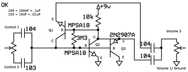
And we're sure that 100N from the emitter of Q1 goes to volume 3 and isn't connecting to the emitters of Q2, Q3, ground, and volume 1? Because that's the only part I still can't see.
Dr Satan wrote:And we're sure that 100N from the emitter of Q1 goes to volume 3 and isn't connecting to the emitters of Q2, Q3, ground, and volume 1? Because that's the only part I still can't see.
As far as I know, here's the schematic ... (I'm still learning how to fully read these guys)
skullservant wrote:I would check your strips and make absoultely sure there is no solder touching accidentally. I like to run an xacto blade over each row just to make sure nothing is touching
I've gone over it numerous times, but I'll go over it again with an exacto knife.
I found the schematic, I just can't verify it on your board. It's the only thing I can't see clearly, and what I can see of it, it looks like it might be wrong. Basically it would be the 104 cap on the right there at the top(of the schematic) is going to ground instead of where it needs to go, and that could make your pedal no trabajo. Those two caps on the bottom right of the vero board should both be on the bottom strip on one end, then one goes to the emitter of the Q1, and the other to the collectors of Q2 and Q3. The ends that go to there respective collectors and emitters appear to be correct, and the second to last one from left to right on the bottom appears to be correct, but I am uncertain of the very last one.
Dr Satan wrote:I found the schematic, I just can't verify it on your board. It's the only thing I can't see clearly, and what I can see of it, it looks like it might be wrong. Basically it would be the 104 cap on the right there at the top(of the schematic) is going to ground instead of where it needs to go, and that could make your pedal no trabajo. Those two caps on the bottom right of the vero board should both be on the bottom strip on one end, then one goes to the emitter of the Q1, and the other to the collectors of Q2 and Q3. The ends that go to there respective collectors and emitters appear to be correct, and the second to last one from left to right on the bottom appears to be correct, but I am uncertain of the very last one.
I'm trying to wrap my brain around this right now, but i can't.
Does this help? E = emitter B = Base C = Collector
What I'm saying is that on the schematic here, the 104 cap that is furthest to the right and on the top, goes between the Volume 3 and the emitter (E) of Q1. But on your VERO board, it looks like the end of that cap that is supposed to go to the Volume 3, looks like it may go to the Volume 1, Ground, Q2 and Q3 collector (C) strip instead. I can't see that part of the board clearly enough to confirm that it is hooked up correctly or not.
Dr Satan wrote: Does this help? E = emitter B = Base C = Collector
What I'm saying is that on the schematic here, the 104 cap that is furthest to the right and on the top, goes between the Volume 3 and the emitter (E) of Q1. But on your VERO board, it looks like the end of that cap that is supposed to go to the Volume 3, looks like it may go to the Volume 1, Ground, Q2 and Q3 collector (C) strip instead. I can't see that part of the board clearly enough to confirm that it is hooked up correctly or not.
Ahh, ok; so are you saying that they should be switched. Please forgive, i'm a total noob. here's some more pictures if this helps.
Everything looks like it is hooked up correctly.(I just labeled the schematic to match the VERO layout) If you're still not getting a signal, it's possible that one or more of the transistors are bad. If you are having to spend a lot of time soldering them(they heat up super fast) you can cook them. You can take an alligator clip and clip it onto the leg you are soldering and it will act as a heat sink to keep you from damaging the transistors. At this point if you still are not getting any signal, you may just want to reflow your solder just to make sure you have no cold solder joints and make sure everything is seated in there with no broken leads.
It's hard to tell but it looks like there is a jumper lead connecting the 9v power lug to the out jack lug. Is that correct? Another way to make sure you didn't bridge any strips is with a multimeter. Set it to continuity and test between two strips, pretty straightforward.


 Does this help? E = emitter B = Base C = Collector
")