substituting caps
Moderator: Ghost Hip
Forum rules
The DIY forum is for personal projects (things that are not for sale, not in production), info sharing, peer to peer assistance. No backdoor spamming (DIY posts that are actually advertisements for your business). No clones of in-production pedals. If you have concerns or questions, feel free to PM admin. Thanks so much!
The DIY forum is for personal projects (things that are not for sale, not in production), info sharing, peer to peer assistance. No backdoor spamming (DIY posts that are actually advertisements for your business). No clones of in-production pedals. If you have concerns or questions, feel free to PM admin. Thanks so much!
-
Bieling2

- involved

- Posts: 52
- Joined: Sat Feb 16, 2013 4:30 pm
substituting caps
yes i googled it first... but can i substitute a 0.01µF capacitor for a 10n capacitor? I can't find a direct answer anywheres.
-
Ben79

- experienced

- Posts: 510
- Joined: Thu Nov 01, 2012 6:16 pm
- Location: Germany
- Contact:
Re: substituting caps
Yes!
1uf = 1000nf (so 1nf is 0.001uf and shifting along by a factor of ten means 10nf is 0.01uf)
1nf = 1000pf
And personally I think the old 'google is your friend' reply is a little cold - I'd rather have human friends
1uf = 1000nf (so 1nf is 0.001uf and shifting along by a factor of ten means 10nf is 0.01uf)
1nf = 1000pf
And personally I think the old 'google is your friend' reply is a little cold - I'd rather have human friends
-
ThePastRecedes

- committed

- Posts: 170
- Joined: Tue Jun 26, 2012 11:03 pm
-
Bieling2
- involved
- Posts: 52
- Joined: Sat Feb 16, 2013 4:30 pm
Re: substituting caps
Thanks for the chart.
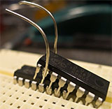
One more quick noob question. The cap in question at first appeared to me to be non-polarized, but there is a black strip around one end and the more I think about it the less I'm sure...
Here is a pic:

Is this a polarized cap? If so is the left side of it with the stripe the positive or negative end?
One more quick noob question. The cap in question at first appeared to me to be non-polarized, but there is a black strip around one end and the more I think about it the less I'm sure...
Here is a pic:
Is this a polarized cap? If so is the left side of it with the stripe the positive or negative end?
-
Ben79
- experienced
- Posts: 510
- Joined: Thu Nov 01, 2012 6:16 pm
- Location: Germany
- Contact:
Re: substituting caps
My thoughts, but I've only been in the game a few months: I doubt it's polarized, as electrolytic capacitors usually aren't made at those low capacitance values and that really doesn't look like an electrolytic cap. I don't know of any other type of polarized cap. If it is polarized, then the stripe would indicate the negative end.
-
Dr Satan

- committed
- Posts: 196
- Joined: Thu Aug 25, 2011 4:11 pm
- Location: North of the ATL.
Re: substituting caps
Ben79 wrote:My thoughts, but I've only been in the game a few months: I doubt it's polarized, as electrolytic capacitors usually aren't made at those low capacitance values and that really doesn't look like an electrolytic cap. I don't know of any other type of polarized cap. If it is polarized, then the stripe would indicate the negative end.
Tantalum caps are polarized. Also, audio grade electrolytics are typically bipolar. From my personal experience with axial electrolytics, the negative side is usually metal where the other side is insulated. This may be highly dependent on the brand, but it is something I've noticed with my admittedly limited use of axial electros.
-
crazynoises
- HERO

- Posts: 31
- Joined: Tue Dec 18, 2012 9:47 pm
Re: substituting caps
Dr Satan wrote:Tantalum caps are polarized.
This.
And while I'm no expert, the cap in the picture looks like it might be an axial Tantalum to me
edit: Something else I just thought of... aside from determining which lead is -, you also have to determine which part of the circuit should get that lead. Unless the capacitor is quite obviously going to ground or +, it can be kind of tricky. So make sure before you put the capacitor in. If you post a schematic maybe someone here can tell you.
-
Bieling2
- involved
- Posts: 52
- Joined: Sat Feb 16, 2013 4:30 pm
Re: substituting caps
I want to put it in the C5 position of the Hipster Fuzz:
http://www.madbeanpedals.com/projects/H ... ipster.pdf
http://www.madbeanpedals.com/projects/H ... ipster.pdf
-
Mike
- committed

- Posts: 467
- Joined: Wed Jun 30, 2010 6:43 pm
- Location: Savannah, GA
- Contact:
Re: substituting caps
Ben79 wrote:And personally I think the old 'google is your friend' reply is a little cold - I'd rather have human friends
But... but... but.... Google really is your friend! They auto-convert if you phrase the search right:
convert .01 microfarad to nanofarad
--or--
.01 microfarad in nanofarad
I use that feature more than I should.
Oh, and looking at that schematic, if it is C5 and you are using a polarized cap, it looks like the the + end should go to R4 and bias, and the - end should go to the volume control.
Mike
My diy pedal blog: Just one more build...
-
McSpunckle
- IAMILFFAMOUS

- Posts: 3848
- Joined: Mon Oct 06, 2008 10:20 am
- Location: Nashville, TN
Re: substituting caps
An easy way to remember this stuff is that pF, nF, and uF are all 1000 away from eachother. So 1uF is 1000 nF, and 1nF is 1000 pF. So just multiply or divide by 1000 to get to the next one and you're good.
-
Bieling2
- involved
- Posts: 52
- Joined: Sat Feb 16, 2013 4:30 pm
Re: substituting caps
Mike wrote:if it is C5 and you are using a polarized cap, it looks like the the + end should go to R4 and bias, and the - end should go to the volume control.
Mike
Great info! Just to reverify then, the left side of the cap with the stripe is the negative end?
-
Ben79
- experienced
- Posts: 510
- Joined: Thu Nov 01, 2012 6:16 pm
- Location: Germany
- Contact:
Re: substituting caps
I think that might be the one piece of advice I gave you that was correct, yes.