Forum rules
The DIY forum is for personal projects (things that are not for sale, not in production), info sharing, peer to peer assistance. No backdoor spamming (DIY posts that are actually advertisements for your business). No clones of in-production pedals. If you have concerns or questions, feel free to PM admin. Thanks so much!
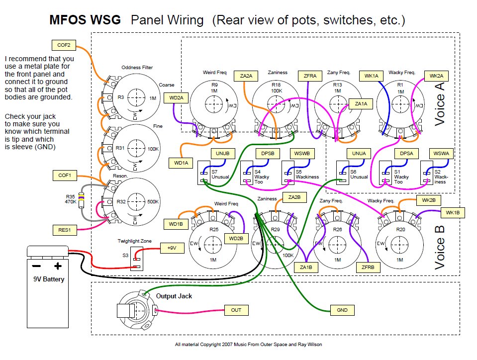
Moustache_Bash wrote:So, still knockin this out at turtle lightning speeds (part of the reason is I didn't buy the kit/PCB, so I've just had it sitting in the breadboard lil bits at a time, but I am also not too smart sooooo) and I was wondering about the jumpers again. In instances where it says "WK1A" would you guys agree it would connect to "WK1B" rather than "WK2A?" My reasoning for that is I would think they would just connect the lines as WK1A and WK2A are on the same page. Then, it seems to change the jumpering lettering a bit, because on page 1 of the schematic you got "COF1" and "COF2." I would assume those are connected as there is no COF# business going on page 2. And finally, RES1. Where the hell does that go? I'm gonna have to look on MFOS' website and see if those connections have some kind of offboard wiring going on or something, or if they don't mind emails from simpletons.
Anyways, if you guys have any ideas I would greatly appreciate it
Moustache_Bash wrote:I'm pretty confused now....
EDIT: Actually not really. Just still not sure about what I mentioned in my previous post.
Where it says "WK1A" on the schematic connects to where the rectangle with the same designation connects on the panel wiring diagram. Same with COF1,2 etc. And same for RES1 actually. If you look at the panel wiring you'll see all of these labels in little rectangles. Take a wire from wherever that point on the schemaic happens to be is on your vero board our however your making it and connect it to where the corresponding rectangle goes on the front panel.
Huh, okay. So, I guess the WK1A/etc is just reiterating itself? From my understanding a lot of these potentiometers/switches would be connected to those areas anyways with or without the WK1A/etc labeling.
Thanks again, multi_s. You're doing me a huge service by answering these questions for me.
Moustache_Bash wrote:Huh, okay. So, I guess the WK1A/etc is just reiterating itself? From my understanding a lot of these potentiometers/switches would be connected to those areas anyways with or without the WK1A/etc labeling.
ya pretty much. i think the labelling maybe makes more sense if you have the PCB and it has labels via the silkscreen on it perhaps. IDK since i dont have one but that is my guess. I built a soundlab about 4-5 years ago by etching the pcb layout he had posted and found the documentation in terms of schematic/wiring is really really confusing and annoying, very much for the same the same sort of things your asking about. not to knock any of his stuff though, just the documentation style could be benefit from being done differently that is for sure.
Moustache_Bash wrote:The WSG looks like it's somewhat similar to the heterodyne space explorer
they are very different. they have nothing in common except maybe they both use a 40106 oscillator. the 40106 is a 6 channel version of a 4049. it is ubiquitous as far as CMOS oscillators are concerned.
multi_s wrote:i think the labelling maybe makes more sense if you have the PCB and it has labels via the silkscreen on it
yes this is %100 correct. the documentation could not be any more noob friendly. those labels are the same on the panel wiring diagram, the PCB, and the schematic. all Moustache_Bash needs to do is read the documentation provided.
multi_s wrote:es this is %100 correct. the documentation could not be any more noob friendly. those labels are the same on the panel wiring diagram, the PCB, and the schematic. all Moustache_Bash needs to do is read the documentation provided.
well, i was not a noob when i built the soundlab and i still found it confusing to wire it all up and follow all the labelling schemes. so i guess it depends on who you are. it is to me a bit silly the way he does it. its like each piece of hardware is drawn twice and also he uses a lot of off board connections and components (I actually made a sub pcb for my soundlab just to more easily connect the 10-20 off board parts) which to me is sort of shifty design, and certainly a pain to work on if anything goes wrong. but again im not knocking any of it. just personally i would do it a bit different.
maybe that is why I like it so much. I use off-board components in my own builds all the time. ok now I see things drawn twice, the coarse + fine and then the CO1 CO2 are redundant. but I think this is to avoid drawing the schematic twice. he would need to omit the PCB labels from the schematic or omit all off-board components in the second schematic. here they are superimposed.
this is how I wired it up. not hard, just time consuming. go slow and read everything twice before you start cutting your long wires is my only advice. the filter is basically a passive design with a buffer. I did not think it was all that special but the parts count is pretty low for a filter.
off board components are terrible imho. might as well go ptp at that point. like hey lets make a pcb to organize all the parts then put half of them floating mid air. haha. to me it jsut looks like lazy design or afterthoughts.
eatyourguitar wrote:they are very different. they have nothing in common except maybe they both use a 40106 oscillator.
Precisely what I meant.
eatyourguitar wrote:
multi_s wrote:i think the labelling maybe makes more sense if you have the PCB and it has labels via the silkscreen on it
yes this is %100 correct. the documentation could not be any more noob friendly. those labels are the same on the panel wiring diagram, the PCB, and the schematic. all Moustache_Bash needs to do is read the documentation provided.
Yeah, no PCB for me.
Also, it works on the breadboard Now to solder it!
multi_s wrote:off board components are terrible imho. might as well go ptp at that point. like hey lets make a pcb to organize all the parts then put half of them floating mid air. haha. to me it jsut looks like lazy design or afterthoughts.
Agreed. No disrespect to Ray, though. He's come up with rad stuff.
Now that's a good comparison to really show how crappy my wiring is! On my next build I'm going to try and match this for neatness, great work eatyourguitar


")