digitalzombie wrote:Hey guys and gals. Just getting into building my kit and I have a couple newbie questions. I've only built a diy mod kit before, so some of my questions might seem really junior level as I'm not going to even try to sound like I know what I'm talking about, but I have asked questions online before so I'll try to be as concise as possible and reference the picture I'm attaching. As you can see I've labeled everything I possibly have questions about on the pictures.
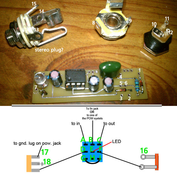
I'm trying to build the single footswitch version to spec, btw:--Question 1: Where do I wire the ground from PCB eyelet 2 to?
--Question 2: I understand the red wire of the LED goes to pole E on the footswitch, but where does the black wire go?
--Question 3: In the diagram, what are the two objects represented on either side of the footswitch diagram (16-18)?
--Question 4: The diagram states "to gnd. lug on pow. jack". Once I get Question 3 answered, is this going to 10 or 12? (I imagine it's one of these since the included instructions make it look like 11 is to be wired to PCB 1.)
--Question 5: Did I receive a stereo jack by mistake? If so, that's fine I can just buy a mono jack from Radio Shack, but curious if I can or even should use the one provided.
--Question 6: Can I just solder a small piece of wire to jump poles I and G on the footswitch? (That's what it's telling me to do, right?)
Um... I think that's all the questions I have for now, but I'm sure I'll have follow ups. Any help would be appreciated. Thanks folks.
I don't know where to begin, but I'll try!
")
Hopefully I get all this correct, cause the number system is confusing me. Also, sorry if I get repetitive with some answers--some of these things are connected (literally!).
--Question 1: The PCB gets grounded to the rest of your ground points. All your ground points get connected together. So PCB ground, LED ground, input jack lug 14/18, (and your power jack ground, if you're not going to use a battery clip) all get connected.
--Question 2: The LED's black wire is ground. That goes to ground. (A good point to run the LED's ground is to the middle lug of the stereo jack, what you have numbered as 14/18.)
--Question 3: Those objects are the jacks...stereo on the left, mono on the right. (Your numbering...14/18 are the same thing, 15/17 are the same thing, and 9/16 are the same thing.)
--Question 4: Ground lug of the power jack is what you have numbered as 10. You only have to connect this to 17 on the stereo jack if you're going to add a battery clip. Otherwise, connect the ground lug of the power jack (10) to ground.
--Question 5: It's a stereo jack, normally used for switching your battery on/off. If you're not adding a battery clip, just ignore that extra lug on the stereo jack (what you have numbered as 17). And run the power jack's ground lug to ground.
--Question 6: That's exactly right.
You have the ground lug of the stereo plug numbered as 14 in the pic and 18 in the diagram...but that lug is your ground point. Number 17/15 gets connected to number 10--ground lug of the power jack. If you're not adding battery operation, forget that lug on the jack...and connect the power jack's ground (#10) to ground with everything else.
Other things......A goes to 4......C goes to 7......B goes to 11......11 also gets connected to 1. On the PCB, 3 and 2 are both grounds...pick one, or use the other to run your LED ground to, if it's more convenient than running your LED ground to 14/18 (ground on the input jack). 9/16 is a ground lug on your output jack. It's left blank.