Forum rules
The DIY forum is for personal projects (things that are not for sale, not in production), info sharing, peer to peer assistance. No backdoor spamming (DIY posts that are actually advertisements for your business). No clones of in-production pedals. If you have concerns or questions, feel free to PM admin. Thanks so much!
I've just finished a Foxx Tone Machine for a friend.
I love the sound but it's compressing a lot. Play a couple of chords one after the other and you can hear the volume drop more than on any other fuzz I've made. You really notice it when you stop playing then start and the first chord you play is higher in volume and clearer sounding than what you've just been hearing.
It's not SUPER pronounced but it doesn't seem right.
Ben79 wrote:I've just finished a Foxx Tone Machine for a friend.
I love the sound but it's compressing a lot. Play a couple of chords one after the other and you can hear the volume drop more than on any other fuzz I've made. You really notice it when you stop playing then start and the first chord you play is higher in volume and clearer sounding than what you've just been hearing.
It's not SUPER pronounced but it doesn't seem right.
I used a Fuzzdog PCB (never done that before because it's cheating! But I didn't have time to build a vero or perf board).
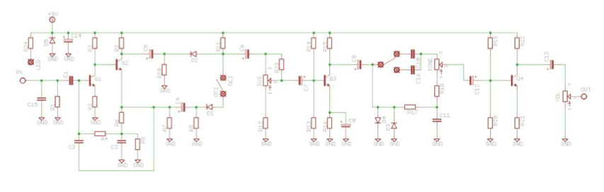
Here's the schem...
And the original schem...
I'll try different transistors and diodes but I'd like to learn something about why this is happening. Can anyone suggest anything?
Thanks for any help.
I just fixed my personal FTM after noticing it was doing the exact same thing. If you have a multimeter and can measure the voltages of all of the transistors it can probably be figured out as it's probably a wrong part somewhere, I'm guessing a resistor. Did you double check all of the resistor values?
You can see how your voltage readings compare to these:
What a coinidence yours was doing the same Laowiz…what was the problem? A bum resistor?
I can measure the voltages. I checked the resistor values but I'll double check them.
THANKS GUYS!
EDIT: voltages checked
MINE GGG
Q1 c 2.21 2.2
b 0.77 0.73
e 0.14 0.16
Q2 c 7.41 7.5
b 2.21 2.2
e 1.59 1.6
Q3 c 6.94 7.28
b 0.8 0.78
e 0.21 0.21
Q4 c 7.75 7.63
b 0.78 0.26
e 0.19 0.84 But I think it's been listed incorrectly on the GGG pdf. What do you think? Why would it suddenly change the order it lists the collector, base and emitter?
If those are your voltages then that's def the problem. I had something like that but for Q3 but remember that I had a 120K resistor where there should had been a 150K. I think that was it and that fixed mine but yours looks to be all around Q4. GG doc looks to be a typo.
The GGG pdf lists the idle bias of the Q4 base as being .58 volts BELOW the emitter? Yeah, I would be suspicious of that as well.
Are you able to track that DC voltage while you play? You'd be looking for a drift "in time" with the compression envelope, my guess is leaning on Q1 as being an indicator and the emitter feedback path from Q2 as being a *potential* culprit. Thing about that sort of bias set up is that it's really designed around the transistor, and your original design Hfe might not be as toppy as what you've got plugged in there. I'm fond of locking in bias with a voltage divider type configuration (like Q3 & 4), but that might very well impact the SOUND of circuit under discussion deployed in the direct coupled pair, so instead of bending the circuit around the transistor, you MIGHT need to select the transistor for the circuit. No need to pluck them all, just the front end stage.
0.7 voltage drop for a Ge diode also seems a touch steep (more like silicon readings).
but I think they have the base and emitter the wrong way round for Q4 which is why my voltages don't match.
Thanks Curt for your insight. I'm gonna read that in the morning when I can concentrate well enough to try to understand it but essentially I should try a lower hfe tranny in Q1 should I?
I tested those diodes on a Peak Atlas so should be right.
Mark Hammer over on another forum suggested a pot between the clipping diodes and ground. What do you reckon?
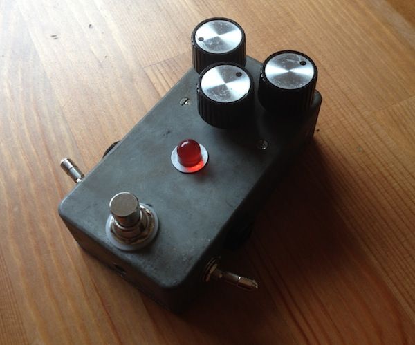
Your voltages look legit as they are very close to GGG, which looks to be a typo. Maybe record a clip of yours. I've made around ten of these and I had a similar prob you described with my last one which I fixed due to wrong resistor values. Maybe post some pics of your build.
A lower value tranny in Q1 may help but I use 200-300 hfe usually. Don't know if Mark Hammer's mode would help but you could try it. Just variable diode clipping, with less clipping the sound will open up more and get louder.
I don't think clipping diodes are going to swing the sort of voltages around that are the root cause of the compression swell you describe, unless that tactic reduces an overbearing signal so it is not tipping a stage into "imbalance". I think the root of your problem is not AC signal related, but wandering DC, I still do not know what's going on at the sections flanking S1.. I mean, I can see the circuitry, I just haven't employed that particular element into any of my builds. Are you absolutely certain your diode polarity is correct here (logically it's a big deal, but again, I haven't built that so who the fuck knows - drunk fairies might fly out and grant you wishes for all I know)?
I also assume when you say you haven't modded the circuit, that means the the capacitor values are also spot on instead of souped up a bit.
Might not need to change the actives at all, it might be a matter of changing the passives to tailor the circuit a little, enough to maintain expected operation without losing the voice/lineage.
Something I do when I'm troubleshooting my stuff is clip a lead with a resistor (vary to taste, but start big) to both Vcc and Common and just poke around while playing. I agree with LaoWiz, changing resistance somewhere will probably resolve the issue if everything else is built per spec (transistor choice notwithstanding).
Well I changed q1 for a 2n2222 and the supercompression has vanished. Still compresses when the gain is way up but the attack is much shorter so it just sounds natural. Before it was under slow and huge compression no matter what the gain setting. Now I'm going to try to understand at least a little bit of why.
I love this pedal. Gonna have to build another for myself I think. I always liked my Superfuzz and Ibanez Standard but these things are so clear and gritty.
Ben79 wrote:Now I'm going to try to understand at least a little bit of why.
If you like to stop everything and crack a book, I've been really happy with Laurence G. Cowles. Early 1970s publish dates, primarily discrete topology, not over-bearing with mathematics, typically he describes stuff in a manner that is fairly easy to digest and provides numerous sample circuit sections for visual learning assistance.
I thought about it when I gutted it but then I just hurled it all into the bin. It was a few big ceramic-looking resistors all soldered very roughly together to what looked like an RF aerial socket. I scored a whole batch of old used enclosures on Ebay for a tenner.