Page 1 of 10
My First Fuzz...
Posted: Thu May 05, 2016 9:53 am
by HighDeaf1080p
Team,
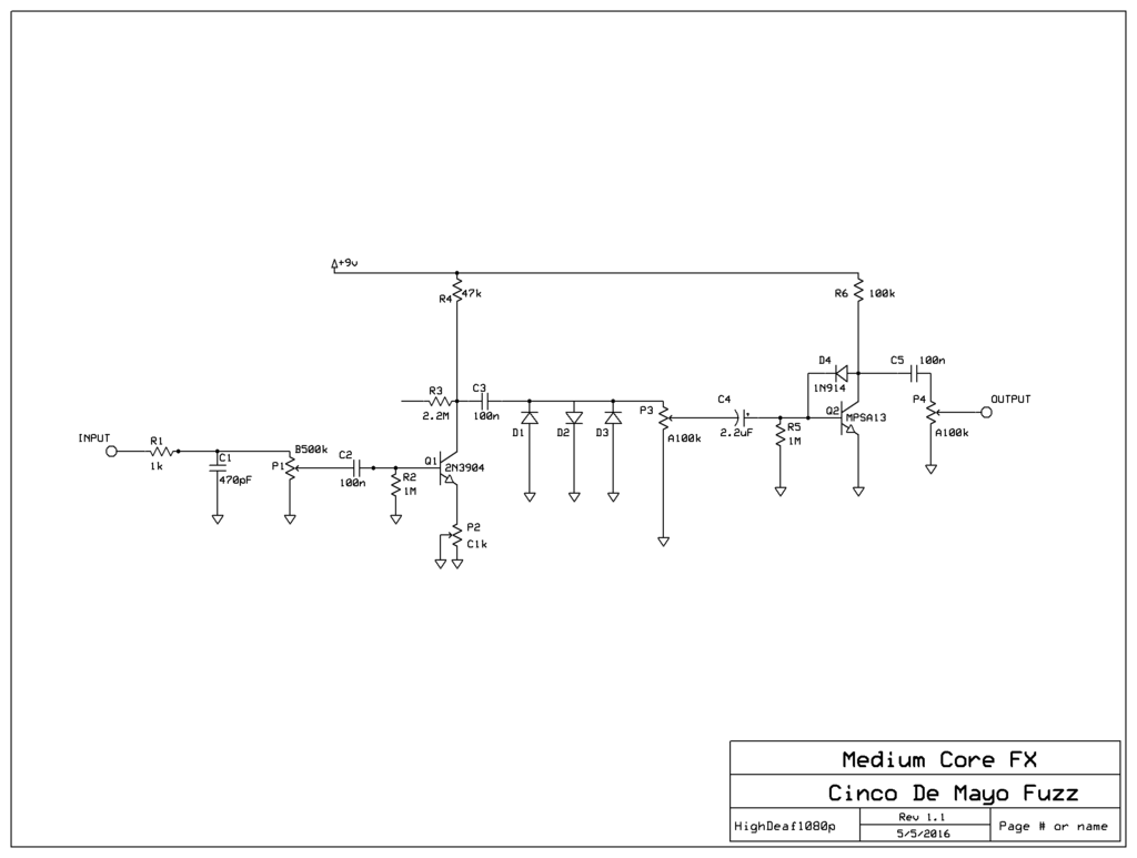
This morning I have attempted to assemble my first fuzz, by cobbling together some schematics found out there on the interwebs. I plan to breadboard it, and test different component values, etc., but can any of you who are long in the tooth see anything blatantly wrong with this from the start?
If this appears sound and will make sound, I can work out the fiddly bits on the breadboard, but if this circuit can't function the way I have it pieced together, any help to get me rolling would be appreciated.
ALSO: this is the very first schematic I have drawn, so I'm very sorry if it doesn't follow some convention, or is really sloppy and reveals my inexperience!!


Lastly,
I have no idea how to take this from schematic to a veroboard layout. Can anyone recommend some softwares or methods I can use?
THANKS!!
Re: My First Fuzz...
Posted: Thu May 05, 2016 10:07 am
by crochambeau
R2 & R5 might do more for you between the DC blocking caps (C2 & C4) and the transistors, in their present position all they are doing is *slightly* changing the taper of the potentiometers.
I'd flip C4 so the + leg faces the transistor base, as you're already blocking collector voltage with C3.
I would expect to have to shuffle some values around, but the circuit looks like a decent starting point and should pass signal unless you have those transistors biased into cutoff.
Regarding translation into actual layout, if you're using breadboard just dive in and think the whole time. If you're using strip or soldered perf I'd grab a pencil and draw it out, but you say breadboard up there, so sort that stage before paving the next as you may run into needed change.
Re: My First Fuzz...
Posted: Thu May 05, 2016 10:31 am
by culturejam
The way P2 is set up, it's not a variable control. It's just going to act as a 10K resistor, which is going to give you very low gain despite the high-value feedback resistor between collector and base.
So connect Lug 2 to ground also.
Also, I'd recommend something like 2K or 1K for that pot value. Most of the pot sweep is going to be very low gain if the high value is 10K.
Move R2 to the input signal. It's not doing much where it is. Also, you can just remove R5. It's not needed.
You might socket C2 and play around with that value. I've found that 100n is a good starting point, but a lot of fuzz does better with something lower (47n maybe).
Re: My First Fuzz...
Posted: Thu May 05, 2016 10:42 am
by HighDeaf1080p
Holy Moly! I learned more from those two posts than I did trying to cobble together the circuits in the first place. Thank you so much guys. Changes made.
culturejam wrote:
Move R2 to the input signal. It's not doing much where it is. Also, you can just remove R5. It's not needed.
You might socket C2 and play around with that value. I've found that 100n is a good starting point, but a lot of fuzz does better with something lower (47n maybe).
I'll be doing the whole thing on a breadboard to allow playing with all the values...is there added benefit to socketing that one on the final board, or is it set once I find a value that works well with my guitar and amp?
As for R2, do you mean to run that one to ground right after the resistor that's already on the input, or run it in series right after R1?
Re: My First Fuzz...
Posted: Thu May 05, 2016 10:58 am
by crochambeau
Reconnect R3 to the base of Q1. The ratio of R3 & R2 is going to define the bias point of Q1, so shifting one of those up/down will resolve sputter at that stage (only).
I just noticed that the orientation of D4 amounts to a near short in terms of dumping collector voltage onto the base of Q2, this might tilt operation of that stage into saturation (not necessarily a bad thing, just a point to consider if you're troubleshooting), so maybe start with a socket there too.
Re: My First Fuzz...
Posted: Thu May 05, 2016 11:05 am
by crochambeau
HighDeaf1080p wrote:As for R2, do you mean to run that one to ground right after the resistor that's already on the input, or run it in series right after R1?
I meant to orient it in the manner you drew, which locks in operating point of that stage, I interpreted culterjam's post in placing that resistor in series. Both methods are electronically viable, but I'd suggest decreasing value if you go with a series resistance.
Please note, the circuit design is not one I typically employ (high value collector resistors on top of no emitter resistor), so I'm speaking from speculation not time tested experience.
Re: My First Fuzz...
Posted: Thu May 05, 2016 11:26 am
by HighDeaf1080p
So what would removing R2 and R5 entirely do to the biasing of the transistors?
As to the near short created by D4...does turning the positive side of C4 away from Q2 change the behavior of that D4?
I'm sure I'll learn tons once it's on the breadboard...and will come back with questions about things I should try. Thank you so much for the great advice guys!
Re: My First Fuzz...
Posted: Thu May 05, 2016 11:28 am
by culturejam
HighDeaf1080p wrote:As for R2, do you mean to run that one to ground right after the resistor that's already on the input, or run it in series right after R1?
Neither.
It's obviously a "pulldown" resistor that was copied from another schematic and left in place (as is R5) . It should be connected in the same manner but directly to the input signal. R5 should be removed. It's another left-over pulldown, and it will cause bias problems because of the diode (D4) feedback arrangement of Q2.
D4 is okay as is (if you ditch R5). That's how a Bazz Fuss is supposed to be setup.

See below:

Re: My First Fuzz...
Posted: Thu May 05, 2016 11:34 am
by HighDeaf1080p
Excellent! Thank you...I'll make the changes and then report back once its all fired up on the breadboard!!
Yes, there are several circuits scabbed together here, haha. Not surprised that I had some vestigal junk hanging around in there.
Re: My First Fuzz...
Posted: Thu May 05, 2016 12:05 pm
by multi_s
also imho there is also not much point to have both D1 and D3 in the circuit if they are similar diodes, ie one could be removed.
Re: My First Fuzz...
Posted: Thu May 05, 2016 12:33 pm
by crochambeau
multi_s wrote:also imho there is also not much point to have both D1 and D3 in the circuit if they are similar diodes, ie one could be removed.
Or you could stack them instead to double the voltage drop (in this case, the signal that remains) for an asymmetrical limit/clip.
culturejam wrote:D4 is okay as is (if you ditch R5). That's how a Bazz Fuss is supposed to be setup.
Aha, I'm looking forward to hearing how this build turns out.
Re: My First Fuzz...
Posted: Thu May 05, 2016 12:50 pm
by HighDeaf1080p
multi_s wrote:also imho there is also not much point to have both D1 and D3 in the circuit if they are similar diodes, ie one could be removed.
D1, D2, and D3 will likely all be different diodes, as I have purchased a selection for trying, so I can come up with my own special blend of herbs and spices. Now I will also try stacking, woot (thank you!)!!
My only remaining confusion right now is around C4. Several of the schematics I've been studying have that capacitor with the positive side towards the transistor, and several have the negative side towards the transistor...a buzz box has one going each way on each of its two transistors...and then still some have a non-polarized capacitor in that location.
Can anyone tell me what that capacitor does, and what might be the advantages of one orientation over the other?
Also, is P1 and P2 doing the exact same thing? P1 hitting the transistor with more or less signal, and P2 adjusting the gain?
Re: My First Fuzz...
Posted: Thu May 05, 2016 12:57 pm
by crochambeau
HighDeaf1080p wrote:My only remaining confusion right now is around C4.
With a polarized electrolytic you want the positive leg sitting on the higher voltage. Since you have another capacitor (C3) in between Q1 & Q2, the higher positive voltage will absolutely be at Q2 (especially with D4 in Bazz Fuss orientation), so position the positive leg toward that - otherwise the electrolytic will be seen as a low value resistance to DC and spill over onto P3, making it noisy.
Re: My First Fuzz...
Posted: Thu May 05, 2016 1:06 pm
by crochambeau
HighDeaf1080p wrote:Also, is P1 and P2 doing the exact same thing? P1 hitting the transistor with more or less signal, and P2 adjusting the gain?
They do somewhat perform the same function, I prefer voltage dividing volume controls (ala P1) AFTER an active stage where it has more signal to work, though the argument could be made for it where it is at. I have gotten away with a P2 like configuration at an early stage, makes for a better GAIN control in my opinion than the P1.
That is not saying you should design one out before the breadboard stage, just keep track of which is which and decide for yourself (sometimes a dual gang is groovy, in that you can adjust two at once, and preset operating point of one stage with fixed resistors, so it won't go full off or will allow you to tailor the response of the control... ..but I'm veering into unnecessary complication there).
Re: My First Fuzz...
Posted: Thu May 05, 2016 1:07 pm
by Nocentelli
R2 seems pointless since you already have a pull down resistor formed by the 500k input level pot, all it will do is slightly reduce the input impedance and alter the taper and value of that pot. R6 should be much lower (e.g. 10k) if you use a Darlington like the MPSA13 (it's only 100k for the first version bazz fuss that used a standard npn transistor like a 2N3904) but you can try higher to see if you can hear a difference.
Good luck with the breadboard experiments.

