Page 1 of 1

OR120 F.A.C control question

Posted: Fri Apr 01, 2016 4:39 am
by AC128
Hey,

since like the OR120 and it's F.A.C. control so much, I would like to add this control to one of my builds.

the schematic clearly shows the caps used, but my question is about the resistor value following the rotary switch
Image

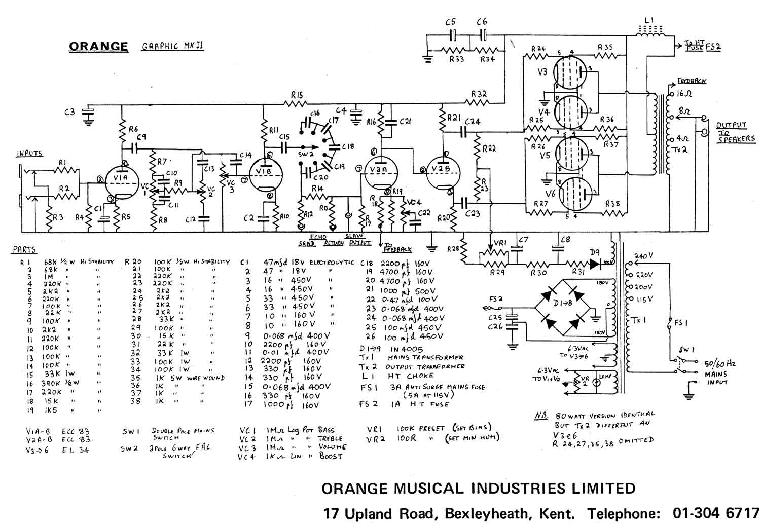
R14 100k and R17 220k are following the switch, so which one would I use if I only wanted to reproduce it's effect?
only the one going to ground (220k)? or do I have to add both resistor values?

Re: OR120 F.A.C control question

Posted: Fri Apr 01, 2016 7:26 am
by SquareWaveFuzz
Neither, the effect of the FAC comes from the capacitors, R14 drops the signal level to compensate for the echo loop, which is what the other two resistors are for :thumb:

Re: OR120 F.A.C control question

Posted: Fri Apr 01, 2016 8:45 am
by AC128
thank you!
I thought the caps at least a resistor form a highpass filter like this
Image

Re: OR120 F.A.C control question

Posted: Fri Apr 01, 2016 6:50 pm
by SquareWaveFuzz
AC128 wrote:thank you!
I thought the caps at least a resistor form a highpass filter like this
Image


Neither of those two resistors that look like they're going to ground are actually going to ground, the nice people at Orange/Matamp put tiny, confusing symbols for jacks in there.

The resistor's going to the tip of the jack and the sleeve is the part that's actually grounded

Re: OR120 F.A.C control question

Posted: Fri Apr 01, 2016 7:19 pm
by crochambeau
The caps do form a sort of high pass filter with the 220K grid leak (R17), though I think R14 might work against this being the classic 1st order high pass pictured. My money would be on simple capacitive reactance via the select switch, surrounding impedances are going to assist in dictating your end result (just tune it by ear, you might have to throw away a few of the listed values).