Page 1 of 1
feedback looper help
Posted: Mon Dec 22, 2008 12:55 pm
by 23F
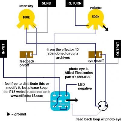
I've built many fuzz, distortion, modulation pedals with great success.. but I cannot get my mind around how to wire the jacks of the feedback looper on the abandon circuits post.I understand which sides of the jacks follow the lines on the layout but do the ground just loop from send to return to outout to volume then to the switch... and will the 9 volt to run the LED still ground to the input? The photo eye doesnt need voltage to work?
some help please? thanks s

Re: feedback looper help
Posted: Mon Dec 22, 2008 3:01 pm
by Slurry
Hey 23F,
I'm about to build a feedback loop myself so maybe I can help you out.
About the grounding issue...
Because this looper doesn't involve a circuit of any kind, the metal enclosure acts as a common ground for all of the jack that touch it. All you need to do is connect the ground lug on your 3PDT switch to any one of your four jacks and it should ground everything. Here's a good reference.
http://experimentalistsanonymous.com/board/viewtopic.php?t=134For the 9v battery, you'll probably want to solder the negative end to the ground lug on the 3PDT switch as well, and put a resistor between the positive end and the LED itself.
And no, the photo eye does not need any voltage to work, It only regulates the voltage going through it.
Re: feedback looper help
Posted: Mon Dec 22, 2008 3:43 pm
by 23F
wouldnt it be a good idea if your using a battery to ground the 9v to the input (stereo jack) then to the switch to act as a cutoff for the LED. Then the third lug wouldnt be connected to anything.just a thought...
by the way thanks, I didnt even think of the enclosure as ground as Im used to not trying to ground out on the enclosure.
")
Re: feedback looper help
Posted: Mon Dec 22, 2008 5:44 pm
by markfrancombe
Slurry wrote:Hey 23F,
I'm about to build a feedback loop myself so maybe I can help you out.
Will you help me too????
Im staring at the diagram to try and get my head round it (yes an electronics newb) And Im guessing that the big square thing at the bottom is the stomp switch... and I spose its ON/OFF for the loop effects?
What Im wondering is, as I dont need to switch OFF my effects that are in the loop, just add the feedback. How can I miss out this stomp switch. Im thinking of making it a "table-top" effect anyway and all my effects live on a rack drawer next to my right hand, not on the floor. (this is just cos Im a constant know twister... (ooh er))
So my finished box should have an overall volume control for.. well everything actually if all my effects are in the loop, or at least comes last... a switch for feedback on off, and knob, and eye on off switch...
hoping someone can take the image into photoshop and re connect a few wires for me+??
Thanks...
Re: feedback looper help
Posted: Tue Dec 23, 2008 12:07 pm
by 23F
Since you've got em all in a rack I would install a 3pdt toggle switch, would be much easier to control with your hand, just incase you want the effect completely bypassed for some reason or another ( might not play well with a certain effect for some reason) other than that the switch poles are in groups which is why it bypasses and can turn an LED on/off. So basically the wires would ne hardwired dependent on the pole connected on the switch.
sorry but Im terrible with posting images on the net and draggin them off the net...
hope this helps maybe someone with a hardwire layout will come along soon...
but again I would install a toggle just incase it doesnt jive with some pedal you have...
Re: feedback looper help
Posted: Wed Dec 24, 2008 11:07 pm
by Skarrgus
Here's an extremely easy way to do it, using only two SPST switches. There's not LED, but it shouldn't be hard to tell when it's on, especially if you're only using toggles.
Also, connect all the ring lugs of the jacks to ground and the Feedback pot should also be 100k Audio taper, though, I'm sure it won't matter too much.
Have fun.
Re: feedback looper help
Posted: Sun Jan 04, 2009 9:47 am
by Nejra Leffor
Slurry wrote:Hey 23F,
I'm about to build a feedback loop myself so maybe I can help you out.
About the grounding issue...
Because this looper doesn't involve a circuit of any kind, the metal enclosure acts as a common ground for all of the jack that touch it. All you need to do is connect the ground lug on your 3PDT switch to any one of your four jacks and it should ground everything. Here's a good reference.
http://experimentalistsanonymous.com/board/viewtopic.php?t=134For the 9v battery, you'll probably want to solder the negative end to the ground lug on the 3PDT switch as well, and put a resistor between the positive end and the LED itself.
And no, the photo eye does not need any voltage to work, It only regulates the voltage going through it.
Heyy Slurry, you seem to know a lot about this feedback looper thing, so maybe you can and want to answer a couple of questions i still have about the diagram

First question, do all the connections that go to the jacks go to the tips of the jacks?
Second question, the ground lug on the 3PDT switch goes to the sleeve of any of the jacks? Or do i have to connect all the sleeves of all the jacks together?
Third question, the potentiometers are a 100k log / audio taper and a 500k log / audio taper right?
The rest is pretty clear i think!
Thanks and i'm sorry for any spelling and / or grammatical mistakes. English is my second language.
Greetings from the Netherlands!!
Re: feedback looper help
Posted: Mon Jan 05, 2009 12:27 am
by Slurry
Nice, I hear they have more bicycles than people in the Netherlands. That's bitchin'
But yeah,
#1 - All of the jacks in the feedback loop are mono (I think) so yes, all of the connections from the 3PDT switch go to the tips of the jacks, not the ground.
#2 - Yes, connect the ground lug from the switch to anyone of the jack's ground lug, then just connect all 4 of the jack's grounds together.
#3 - I would say that both the 100K and 500k pots are linear, but you could use an audio tapered pot for the 500k if you wanted. I don't think it would make much of a difference in this pedal.
Damn, I still got to get around to making mine.
When I do, I'll try to take pictures and such.
Re: feedback looper help
Posted: Mon Jan 05, 2009 8:54 am
by Nejra Leffor
Slurry wrote:Nice, I hear they have more bicycles than people in the Netherlands. That's bitchin'
But yeah,
#1 - All of the jacks in the feedback loop are mono (I think) so yes, all of the connections from the 3PDT switch go to the tips of the jacks, not the ground.
#2 - Yes, connect the ground lug from the switch to anyone of the jack's ground lug, then just connect all 4 of the jack's grounds together.
#3 - I would say that both the 100K and 500k pots are linear, but you could use an audio tapered pot for the 500k if you wanted. I don't think it would make much of a difference in this pedal.
Damn, I still got to get around to making mine.
When I do, I'll try to take pictures and such.
Thanks a lot for the help man!! I'll make one as soon as i can. Usually that means as soon as i have some money hehe

Haha, look i'm bleeding from the anus!
We do have more bicycles than people in the Netherlands. But that's because we always forget where we left our bike and buy a new one after coming from the coffeeshop, if you know what i mean.
Take care and thanks again!
Still bleeding...
Re: feedback looper help
Posted: Sun Jan 25, 2009 8:19 pm
by Slurry
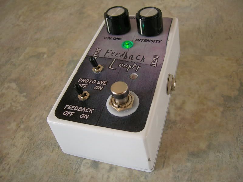
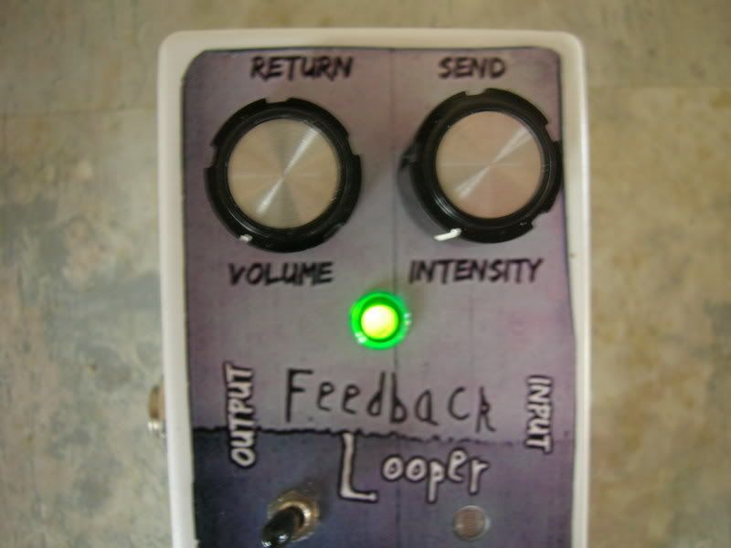
Here's my completed Feedback Looper pedal. Haven't got a video yet, but I'll post one when I find some cool sounds.
Re: feedback looper help
Posted: Fri May 07, 2010 12:19 pm
by lama00
I'm late, I know but could anybody tell me the value used for the photocell ?
Thanks