Page 1 of 2
Stereo Memory Man
Posted: Wed Sep 22, 2010 9:31 pm
by Jero
I need some good gut shots of your stereo memory man. I'm in the process of fixing mine (hasn't worked ever) and want to check over a few spots. More details later.
Re: Stereo Memory Man
Posted: Wed Sep 22, 2010 9:47 pm
by Scruffie
Sell it to me! Give ya 50 Bucks for it

But which model is this, is this the one you mean?

What chips does it have aswell, there were several versions.
Here's a good gut shot of the back of the PCB

And a bad shot of a deluxe version which might help

Another model

Re: Stereo Memory Man
Posted: Wed Sep 22, 2010 10:58 pm
by Jero
Scruffie wrote:But which model is this, is this the one you mean?
What chips does it have aswell, there were several versions.
Here's a good gut shot of the back of the PCB
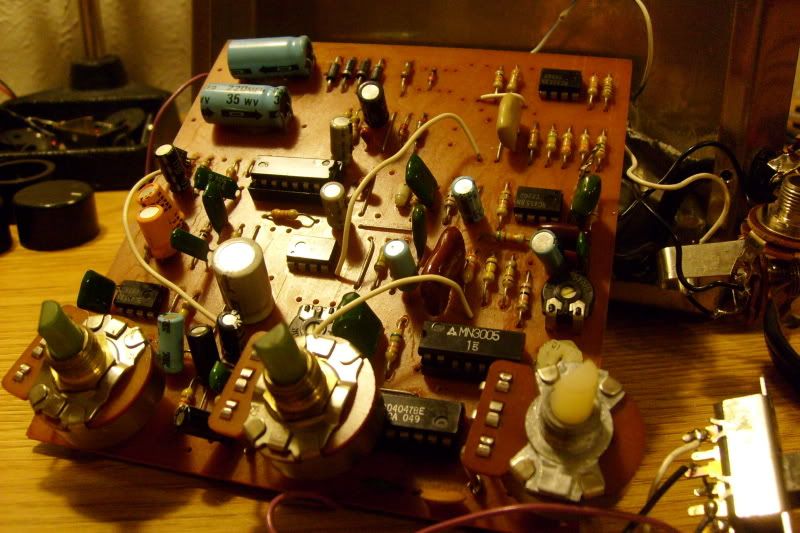
That's the one (I can see the number on the pcb). The blend/feedback are switched in mine compared to the first pic you posted. It's the same one I told you about from a while back. Here's some shots...

Re: Stereo Memory Man
Posted: Wed Sep 22, 2010 11:06 pm
by Scruffie
You'll want this
http://img.photobucket.com/albums/v517/ ... myMMan.gifVoltages at all the pins will be helpful to debug it.
Re: Stereo Memory Man
Posted: Thu Sep 23, 2010 12:07 am
by tuffteef
if i could work it out i would work out the reason why the oscillations on the memory sound so amazing and only come from the memory man
it sounds like its having a heart attack its thumping in your chest/a dying computer and never gets ratty and ear piercing like newer analog delays

Re: Stereo Memory Man
Posted: Thu Sep 23, 2010 2:45 am
by devnulljp
Those electrolytics are pretty old -- even if they're not *the* problem they're more than likely *a* problem and bonus is they're a 10 min fix.
What's wrong with it?
Re: Stereo Memory Man
Posted: Thu Sep 23, 2010 3:56 am
by Jero
Appreciate the schematic Pete!
All the connections are made, everything looks solid, but the unit won't power on. I need to check the tran. I tried earlier and it just showed up as a "-". I'll change the caps too, can't do that one just yet though.
Re: Stereo Memory Man
Posted: Thu Sep 23, 2010 9:01 am
by Scruffie
Jero wrote:Appreciate the schematic Pete!
All the connections are made, everything looks solid, but the unit won't power on. I need to check the tran. I tried earlier and it just showed up as a "-". I'll change the caps too, can't do that one just yet though.
No Worries,
Yeah... infinity is never a good reading, replacing that will hopefully get you voltages on it. Electrolytics can work for 50 years and none of those 'look' bad but that's not to say they haven't gone bad (although some look like they might've been replaced already) you'll probably save yourself some hassle replacing them anyway though and probably cut down on unit noise when it does work.
Re: Stereo Memory Man
Posted: Thu Sep 23, 2010 11:38 am
by Scruffie
Here we go, a nice clear gut shot of your model -

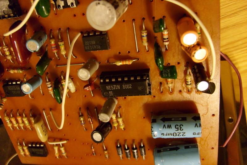
You can see what I mean about thinking some of the Electrolytics had been replaced, those black/yellow ones are almost definitley newer than the blues I think, plus you don't have tantalums in several of the places in your unit (Not that, that would be an issue for it to not work) although EHX was known for using what was on hand... I think it's been tampered with in the past.
Here's how i'd go about repairs...
- Check the Switches with a DMM to see if they work, you'll almost certainly need to use contact cleaner on them if not replace them, they go alot on old EHX pedals i'm led to beleive.
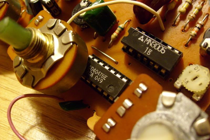
- Clean the back of the board up and reflow any bad looking joints (be careful of soldering heat especially around the 4047 & 3005 though) the pots will have been under mechanical strain over the years from being board mounted so they're your main concern for bad joints.
- Check all chips are properly seated and contacts are clean and making good connection in there sockets (they look okay from the picture though)
- Check the board is getting proper voltages (as you've started doing and have found a possible problem at the transistor)
- Post up all your voltages so they can be checked over
- Once the unit is working, you're probably gunna have to re-bias the unit to be honest to get the most out of it.
Re: Stereo Memory Man
Posted: Thu Sep 23, 2010 12:55 pm
by Jero
Scruffie wrote:Here's how i'd go about repairs...
Yea, I can def tell a bunch of the electros have been changed. The ceramic cap directly above the 3005 has also been changed to a massive film cap (which ironically showed up in every pic I posted).
To be clear, I checked the transformer (not transistor) across it's board connections and I got a negative sign. Means there's no power going through it right? Seems like that might be the first thing for me to swap would you agree? Also, would I just get any 24v one? The first thing I did was check all connections, solder joints, and whatnot. Also made sure the chips were sitting right (and even reseated the ones that were socketed).
How do I go about checking switches with my meter? It doesn't have a continuity test or some of the other stuff. I had to sell off my nice one and then got this cheap one to tide me over. It has dc volt, dc current, ac volt, resis, transistor, diode, and battery tests.
Re: Stereo Memory Man
Posted: Thu Sep 23, 2010 1:01 pm
by devnulljp
Pretty sure you should be getting something like +/-15V from the transformer to ground, so that looks to be the most likely culprit?
Re: Stereo Memory Man
Posted: Thu Sep 23, 2010 1:11 pm
by Scruffie
Yeah you need a new Transformer, unless it's one of the diodes, are you measuring straight at where it comes into the board? Just to be sure, those Diodes are there to drop the voltage down from the 24V to 15V.
You could just say sod the transformer and buy a wall wart for it though with a bit of modding, don't know if you want to keep it original or not, transformers can add alot of noise though so it might be an idea.
The transformer You want though is one that's whatever your wall voltage is down to 24V Yeah (110 to 24?) i'll have to have a look where to find a suitable one... remember the dangers of doing such a thing though...
Switch testing, you can do it with resistance, put your leads onto the 2 contacts you want to test between, when the switch is open you should get a value of 1 (higher than your multimeter can read) when closed a low resistance, aslong as you know what lugs are doing what you should be able to work it out from that.
Re: Stereo Memory Man
Posted: Thu Sep 23, 2010 2:47 pm
by Jero
devnulljp wrote:Pretty sure you should be getting something like +/-15V from the transformer to ground, so that looks to be the most likely culprit?
That's what I was thinking
Scruffie wrote:You could just say sod the transformer and buy a wall wart for it though with a bit of modding, don't know if you want to keep it original or not, transformers can add alot of noise though so it might be an idea.
The transformer You want though is one that's whatever your wall voltage is down to 24V Yeah (110 to 24?) i'll have to have a look where to find a suitable one... remember the dangers of doing such a thing though...
Yes that, lets do that (wall wort)...I'm always a scared when messing with transformers, how should I go about it?
BTW, I measured directly where it connects to the board. I'll make a circle around it in the picture. That switch check with the resistance is nice to know.
Re: Stereo Memory Man
Posted: Thu Sep 23, 2010 9:43 pm
by Scruffie
Jero wrote:devnulljp wrote:Pretty sure you should be getting something like +/-15V from the transformer to ground, so that looks to be the most likely culprit?
That's what I was thinking
Scruffie wrote:You could just say sod the transformer and buy a wall wart for it though with a bit of modding, don't know if you want to keep it original or not, transformers can add alot of noise though so it might be an idea.
The transformer You want though is one that's whatever your wall voltage is down to 24V Yeah (110 to 24?) i'll have to have a look where to find a suitable one... remember the dangers of doing such a thing though...
Yes that, lets do that (wall wort)...I'm always a scared when messing with transformers, how should I go about it?
BTW, I measured directly where it connects to the board. I'll make a circle around it in the picture. That switch check with the resistance is nice to know.
Yeah transformers are a tad unfriendly...
Okay... we have a Bi-Polar Supply here... two options you re-work a 24V supply to do it, or you use a LT1054 Doubler chip to do it for you (easy option, providing this doesn't draw more than 100mA, also allows it to work from a standard 9V supply)
Study the LT1054 datasheet and this article
http://www.geofex.com/circuits/+9_to_33.htm i'll be back later with more info...
Re: Stereo Memory Man
Posted: Fri Sep 24, 2010 4:20 pm
by nbabmf
A simpler solution would be to add a DC jack right where the transformer output is and use a Dunlop 18V adapter. The voltage regulator wont't have to work nearly as hard to step it down to the 13-15V those BBDs want to see and you won't get any weird noise from a LT1054 voltage doubling board.