Page 5 of 10
Re: My First Fuzz...
Posted: Thu May 26, 2016 10:06 pm
by eatyourguitar
the power filtering caps can definitely make it more muddy. Maybe people dont believe it but i have tested it. It does not however explain the reduction of gain. I would suspect a larger value resistor was used on either the base, collector, or emitter. Try to measure them in circuit with power off.
Re: My First Fuzz...
Posted: Thu May 26, 2016 11:03 pm
by crochambeau
Also measure the voltages/etc at your transistor legs (all of them, in a chart) and compare that to the breadboard.
Re: My First Fuzz...
Posted: Fri May 27, 2016 8:20 am
by HighDeaf1080p
Ok, I can do all that tonight, easy enough.
I purchased just the parts for the build the first time...and put them into the breadboard...then I duplicated that order to get the parts for the permanent vero-board layout...so I'll be surprised if one of the resistors is wrong, because it would have had to be the wrong part shipped to me, and labeled wrong in the bag...but stranger things have happened. I'll compare all the stripe codes, and measure them in circuit and see what I get. I believe the germanium diode is ok, because it still seems to give me that germanium squeel with the warping pot turned to the right...and gives me that silicon grit to the left...and everything in between as you turn between them. I'll measure that diode too, though. I'll do all of that with the battery disconnected.
When measuring the voltage at the legs of the transistors, where do I place the test probe leads? negative on ground, and positive on the leg of the transistor? I assume I do these tests with the battery hooked up?
I'll get these measurements and report back. The other problem may be that I'm hooking the board to the breadboard's positive, negative, input, and output...WITH the other layout still on the board. Maybe I need to use its own breadboard tonight, with only battery, and input/output jacks on it...and none of the original circuit.
Either way I may pull the power filtering, and see if I like that better as well. Removing variables will help too, and the breadboard does not have the power filtering.
Also: could bad solder joints be adding resistance, and reducing gain? Given I'm so new at this I have no confidence that my solder joints are correct.
The good news is, its sounding pretty good already, and was easier than I expected when I started all of this. If I can get the output volume up to the level of the breadboard I think it will sound the same, and I'll be at the finish line! Woot! If I CAN get it to sound as good as the breadboard, it will probably be the best dirt pedal I own. Right now it sounds "pretty good" but very compressed, somewhat muddy, and uninspiring. And it seems pointless to have all those knobs that have to be fully cranked to get any sound or distortion out of the pedal, whereas on the breadboard version they all do great things to give me new sounds.
Thank you Eatyourguitar and Crochambeau for all the phenomenal help. I could not have made it this far without you guys!
Re: My First Fuzz...
Posted: Fri May 27, 2016 8:29 am
by HighDeaf1080p
Oh, also, one other really newbie question that keeps tripping me up.
With resistors...less resistance (smaller numbers) will give me more voltage and current, right? But with transistors...I'm guessing more resistance on the emitter raises gain, but more resistance on the collector or base...will that lower gain? I'm kind of imagining a transistor like an oven, and the more voltage/current I cram in there, and not let out, the hotter (higher gain) it gets?
OR...should I think of a transistor just like a super-diode, and the less resistance all around allows more voltage to flow through it, and therefore gives more gain?
What's really throwing me off on this is the C1K pot between the 2N5088 and ground that is working backwards from the one on the breadboard. It's also working backwards from the pot between the 2N3904 and ground on both the breadboard and the soldered board. I have triple checked pins 1 & 3 and they are definitely hooked up the same, so I'm starting to think one of them is labeled wrong, and is an A1K or something...its insane. At any rate, I will probably just reverse pins 1 & 3 on the build and move on with my life, but I wanted to at least understand what I'm trying to achieve in regards to high resistance on the emitter vs. low resistance on the emitter.
Re: My First Fuzz...
Posted: Fri May 27, 2016 9:51 am
by crochambeau
HighDeaf1080p wrote:When measuring the voltage at the legs of the transistors, where do I place the test probe leads? negative on ground, and positive on the leg of the transistor? I assume I do these tests with the battery hooked up?
Place the ground reference lead on your common/ground point and leave it there, probe with just the red lead. Yes, battery is connected, you might wind up doing this while feeding signal through the circuit as well (only you'll be measuring AC then, unless you have a scope), but one thing at a time.
HighDeaf1080p wrote:With resistors...less resistance (smaller numbers) will give me more voltage and current, right?
No, not necessarily. It depends on how the resistor is placed in circuit.
HighDeaf1080p wrote:But with transistors...I'm guessing more resistance on the emitter raises gain, but more resistance on the collector or base...will that lower gain? I'm kind of imagining a transistor like an oven, and the more voltage/current I cram in there, and not let out, the hotter (higher gain) it gets?
No, I haven't had enough coffee to articulate yet, but again - everything boils down to how you employ the transistor in circuit.
The backwards functioning pot still might be installer error, never convince yourself otherwise. You'll wind up catching so many blunders as you follow this path, part of the fun really.
Re: My First Fuzz...
Posted: Fri May 27, 2016 9:55 am
by HighDeaf1080p

It's gotta be install error, I just cant figure out how...I set the two side by side and they are wired identical...its hysterical.
At any rate, I have a whole 3 day weekend to figure things out with this. I will just start methodically measuring resistances, voltages, diodes, and following paths, until I find some differences.
Cuz I really really WANT the sound that's on the breadboard. Its fantastic.
Re: My First Fuzz...
Posted: Fri May 27, 2016 9:59 am
by eatyourguitar
HighDeaf1080p wrote:The other problem may be that I'm hooking the board to the breadboard's positive, negative, input, and output...WITH the other layout still on the board. Maybe I need to use its own breadboard tonight, with only battery, and input/output jacks on it...and none of the original circuit.
this is definitely what caused the problem. disconnect the input, output, +. - from the breadboard circuit. also, you do not need power filter caps on a battery powered circuit ever. I would actually advise against it. don't need to remove it though since you already soldered it in. there are a few reasons why gain is reduced. the two volume pots on the output will shunt more current in parallel than a single volume pot. you might have one of them turned down right now. the lowest knob does the job. they both need to be at 11 for this to be close to full volume. remember they are not 100k when you put them in parallel and have them both fully CW. they actually function like a single 50K pot fully CW.
Re: My First Fuzz...
Posted: Fri May 27, 2016 10:02 am
by HighDeaf1080p
ah hah! I did disconnect the input and output, but left the power to the breadboard circuit connected. I'll try that first! Would be super awesome if suddenly everything worked as expected. hehe.
Correction: I just realized I disconnected the OUTPUT ONLY from the breadboard circuit...so the input from the guitar was going through both the breadboard circuit and my soldered circuit...and power was going through both...
Hopefully that explains the problem.
I'll put my soldered circuit on its own power and input/output tonight and see what I get.
Re: My First Fuzz...
Posted: Fri May 27, 2016 10:28 am
by eatyourguitar
HighDeaf1080p wrote:Oh, also, one other really newbie question that keeps tripping me up.
With resistors...less resistance (smaller numbers) will give me more voltage and current, right?
a resistor connected directly to the +/- of a power source like a battery will consume more current with a smaller resistor. example 1K = 1000 Ohms will let enough current through for an LED. 10R = 10 Ohms will draw much more current and damage the LED.
HighDeaf1080p wrote: But with transistors...I'm guessing more resistance on the emitter raises gain, but more resistance on the collector or base...will that lower gain?
adding resistance to the emitter will ALWAYS reduce gain. adding a resistor to the base (and ONLY one resistor) will ALWAYS reduce gain. collector resistor will increase gain if the new resistor is closer to the theoretical maximum gain circuit for that configuration. you could go to infinity reducing the size of the collector resistor in a common emitter style circuit but you would be building something that makes square waves, the distortion makes the circuit useless so it is considered out of operating range, not really defined as maximum gain in the purest sense. you would also hit a limit where the transistor will never consume more current than the small resistor and at this intersection on the graph we are actually reducing gain.
HighDeaf1080p wrote:I'm kind of imagining a transistor like an oven, and the more voltage/current I cram in there, and not let out, the hotter (higher gain) it gets?
not at all. I prefer to use heat to describe heat in semiconductors. heat sucks, when you have too much watts, your stuff gets hot and dies.
think of a transistor as a flashlight controlled flashlight. the more direct light (voltage) hitting the base, the more the big flash light will turn on. this big flash light get brighter and brighter until it is at 11 and then it just stays the same. this is like a 2N3904 fully ON and dissipating 1W of power through the case of the transistor to the air as heat. if you put it in a box and create an oven, a real oven, you will make it difficult for the transistor to dissipate 1W continuously. this is what causes failure. and you are stuck without a really big flash light.
Re: My First Fuzz...
Posted: Fri May 27, 2016 5:35 pm
by HighDeaf1080p
Okay...so far, here's what I've got:
Diodes:
1N270: 2.54v (breadboard), 2.38V (veroboard)
1N4001's: 5.46 and 5.45 (breadboard), 5.41 and 5.45 (veroboard)
1N914: 5.80 (breadboard), 5.81 (veroboard)
To me that says diodes are all fine and relatively identical.
Resistors:
All match values as expected. Only anomaly noted was that the 12k resistor between the "graft" pot and ground is missing on the breadboard. How big of a change will it make to remove that one extra resistor to ground?
Now...as for the voltage measurements on transistor legs...I had to use both my meters to get readings, and they weren't consistent, so I don't know what to do or what I'm doing wrong. Fluke kept giving me overlimits or just beeping on some legs.
2N3904 from breadboard:
Vici meter - C = 3v, B = 2.182v E = 1.79v
Fluke 113 - C = O.L. B = 1.42v E = .83v
2N3904 from veroboard:
Vici meter - C = 2.4v B = .684v E = .2v
Fluke 113 - C = O.L. B = no reading E = beep
2N5088 from breadboard:
Vici meter - C = .758v B = 554mv E = .8v
Fluke 113 - C = .891v B = 2.181v E = beep
2N5088 from veroboard:
Fluke 113 - C = .585v B = 1.115v E = .572v
Didn't take readings with the Vici on this transistor.
So I set up the board on a totally isolated breadboard with power and input/output, and the volume and gain problem persists.
Have no idea if the problem is a fried transistor or what because I can't seem to reliably get the meters to read out, or have consistent unit of measure. Not sure why that one leg would only read in mV. But the problem is clearly persistent, and other than taking out the one 12K resistor, the only idea I have from here is pull the transistors off the breadboard and use them in the vero board. *shrug*
The volume difference between the two is HUGE. When I set the volume on the amp so that the vero board is still too quiet but loud enough to at least hear details...when I switch to the breadboard it is LOUD. I would guesstimate twice the volume between the two, and the veroboard version has no in-betweens...it goes from no sound (40% of the knob), to clean (50% of the knob) to full distortion/saturation/compression (final 10%).
The breadboard version is nice smooth transitions in gain, from reasonable volume up to VERY loud, and all levels of distortion/break-up/etc.
I feel like some part is faulty...but how do I find the broken thing out of all of it? And why are my meters reading completely different on voltage?
Re: My First Fuzz...
Posted: Fri May 27, 2016 6:09 pm
by eatyourguitar
bro your fluke is set to resistance. OL is open load. the resistance is too big to measure so it assumes wire disconnected, open circuit. the beep is a continuity tester that happens when resistance < 50 Ohms. if it beeps when testing voltages, you have the meter wrong. when you have the meter in resistance, you should always have power disconnected. don't worry though, you got good measurements on the other meter.
I think you have the aggitate pot set differently on one of them. also I would suspect that 2M2 with %20 or %10 tolerance can make the difference in gain between two silicon transistors even more noticeable. even R4 and P2 are +/- %10. the 2N3904 is about +/-%10 Hfe. set both pots to 0 check voltages. set both pots to 10K check voltages
Re: My First Fuzz...
Posted: Fri May 27, 2016 6:17 pm
by HighDeaf1080p
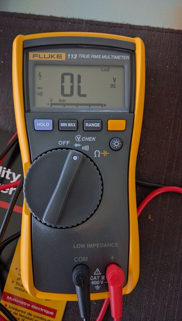
It has one setting for voltage, continuity, and diodes...and on that setting it starts up with OL on the screen. When I tested those legs...OL stayed on the screen.
But...I've found that when I manually set the range to 0.000 volts...and then test those legs...it stays at 0.000...whereas adjacent legs give me readings of .671 and .781v or similar.
At least the fluke reads 0.000 when I set it that way until I test something...the Vici has numbers just swimming up and down unless the leads touch eachother...then it zeros out and stays put.
Re: My First Fuzz...
Posted: Fri May 27, 2016 6:24 pm
by eatyourguitar
we were both wrong. you have it set to diode tester. I just got the manual.
http://media.fluke.com/documents/113_____iseng0200.pdf
Re: My First Fuzz...
Posted: Fri May 27, 2016 6:27 pm
by HighDeaf1080p
Hahaha. How confusing. Cuz there's only one setting for all those things. One spot on the dial, and no yellow options to switch to with the yellow button. It is SUPPOSED to figure out what you're trying to do and read correctly, but clearly it is not doing that.
It touts "check voltage and continuity at the same time". *sigh*
Re: My First Fuzz...
Posted: Fri May 27, 2016 6:33 pm
by HighDeaf1080p
At any rate, every time I test it, with EITHER meter, I get totally different readings and some legs that give me no readings...on both boards. So I'm batting 1000 on voltage testing this thing.
