Page 340 of 408
Re: Let's see your finished DIY projects!
Posted: Thu Mar 02, 2017 3:13 pm
by cherler
Strange Tales wrote:Yeeep, all hand soldered. Just need a flux pen, a fine tip, and a steady hand.
I don't drag solder, everytime I've tried that I get at minimum 3 or 4 bridges across pins.
I cover the pads in flux, place the chip, and then put a tiny bit of solder on my tip. I then put down the two opposite corners so the IC is in place. Then I reapply solder to the tip and just go right in, cover the leg, pull out, do the next leg... and so on. Probably not the best way but it's what works for me.
Invisible Man wrote:This is some Persian Carpet level nonsense.
Yeah holy shit haha, still looks great!
Re: Let's see your finished DIY projects!
Posted: Thu Mar 02, 2017 3:19 pm
by comesect2.0
awesome job strange tales. ....''persian carpet..tiny hands...'' haaahah.
Re: Let's see your finished DIY projects!
Posted: Thu Mar 02, 2017 3:22 pm
by Strange Tales
I DON'T APPRECIATE THESE TINY HAND JABS.
I am going to get a gypsy to curse you with tiny hands IM, then the tables will turn.
Re: Let's see your finished DIY projects!
Posted: Thu Mar 02, 2017 3:23 pm
by cherler
I'm gonna get SO GOOD AT SOLDERING
Re: Let's see your finished DIY projects!
Posted: Thu Mar 02, 2017 3:30 pm
by comesect2.0
lock them out and block the door bar them out forever more!
change the lock and change the door smear them out forever more
curse go back curse go back back with double fear and flack
silver arrow threw the night silver arrow take they flight
silver arrow seek and find cursing heart and cursing mind!!!!!!!!!!!!!!!!!!!!!!!!!!!!!!!!!!!!!!!
Re: Let's see your finished DIY projects!
Posted: Thu Mar 02, 2017 8:13 pm
by crochambeau
That tip is nightmare fuel.
Re: Let's see your finished DIY projects!
Posted: Mon Mar 06, 2017 9:58 am
by cloudscapes
You don't even have to touch. The solder melts out of fear from just looking at it.
Re: Let's see your finished DIY projects!
Posted: Wed Mar 08, 2017 4:50 am
by agiant
My first one, rangemaster with a ac188 ge transistor
Re: Let's see your finished DIY projects!
Posted: Thu Mar 09, 2017 12:00 am
by digi2t
Not finished yet, but another WOW Signal Fuzz, but with a big can CA1558, and a nice Sanyo 2SB405 that I salvaged out of an old tape deck.


The one I made for Jimi got a good review, so I figured I'd add one to my herd as well. This one is voiced a bit different, it's got a "Big Muff with a zipper" feel.
Here's the vero for those that want to give it a shot;

Just a couple of notes;
- R13 can be anywhere between 1K and 4.7K. It's the current limiter for the LED, so adjust to taste.
- R10 I replaced with a 50K trimmer. 5.25v is OK but depending on the Germ, this will shift. With some transistors, this voltage is too high, and it reduces (or negates) the effectiveness of the gain pot, i.e. gain sounds maxed no matter where you set it. The ideal is to reduce base voltage until the signal cuts, and then slowly come back. Sweep the gain to see if there's a decent min./max. gain differential, and you should be good to go. Set the voltage as high as possible, without overriding the gain pot.
- C7 is 82pF in the original, but there's a lot of fizz. Depending on your final choices for transistors, I found that anything between 470pF, and 1nF tends to be more comfortable on the ears. I've even gone as high as 2.2nF, but it's much darker then, and starts to cut into the effectiveness of the filter. The one that I'm building now has an 820pF, and it's just crunchy enough. I socketed all the transistors, and that cap for testing. Once the final actors were chosen, I soldered the silicons to the sockets, and the Ge and cap went direct to the board.
ADDED NOTE: If the Filter control is too dark for your taste, then replace C11 with a 10n, and the pot with a A10K. This will give it more of a "Mids presence" control.
Re: Let's see your finished DIY projects!
Posted: Fri Mar 10, 2017 6:11 pm
by Strange Tales

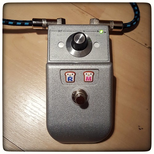
Simple build (Eurorack Module Tester) but man it's going to be so much easier to calibrate VCOs and shit now.
Re: Let's see your finished DIY projects!
Posted: Sat Mar 11, 2017 1:11 am
by imJonWain
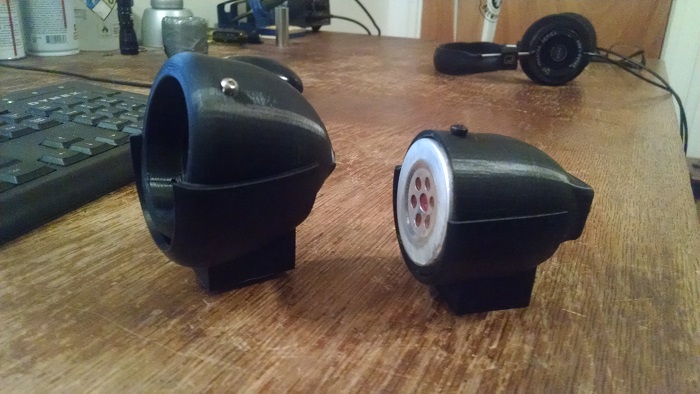
I designed and 3d printed some harmonica mic style shells & mic stand mounts for my telephone mic (I previously had it in a mouthwash cap with duct tape. The bigger one I found the mount itself online already and I made a shell the same size as an actual bullet mic, it's seemed big so I made the smaller one after.
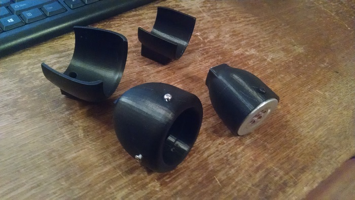
- 3dmic.jpg (226.56 KiB) Viewed 4440 times
- 3dmic2s.jpg (222.63 KiB) Viewed 4440 times
Re: Let's see your finished DIY projects!
Posted: Sun Mar 12, 2017 4:22 pm
by spacelordmother
Are you just wiring the 2 terminals on the mic to a jack or TS cord?
Re: Let's see your finished DIY projects!
Posted: Sun Mar 12, 2017 5:04 pm
by imJonWain
yeah just wiring it straight to a 1/4" jack
Re: Let's see your finished DIY projects!
Posted: Sun Mar 12, 2017 8:19 pm
by Invisible Man
Strange Tales wrote:I DON'T APPRECIATE THESE TINY HAND JABS.
I am going to get a gypsy to curse you with tiny hands IM, then the tables will turn.
Sorry/not sorry.
Your gypsy curse would explain a lot of recent events, actually...and Tiny Hand Jabs is the name of our drums/euro noise duo.
Re: Let's see your finished DIY projects!
Posted: Sun Mar 12, 2017 9:51 pm
by spacelordmother
imJonWain wrote:yeah just wiring it straight to a 1/4" jack
That's awesome! Cool housings, mang.


