You are correct then to refer to the protective qualities the current limiting resistor provides. Looks good, can't wait to hear some clips!HighDeaf1080p wrote:I do care about the LED burning out quickly, which I understand will happen if you don't use a resistor or some kind.
My First Fuzz...
Moderator: Ghost Hip
Forum rules
The DIY forum is for personal projects (things that are not for sale, not in production), info sharing, peer to peer assistance. No backdoor spamming (DIY posts that are actually advertisements for your business). No clones of in-production pedals. If you have concerns or questions, feel free to PM admin. Thanks so much!
The DIY forum is for personal projects (things that are not for sale, not in production), info sharing, peer to peer assistance. No backdoor spamming (DIY posts that are actually advertisements for your business). No clones of in-production pedals. If you have concerns or questions, feel free to PM admin. Thanks so much!
-
crochambeau

- IAMILF

- Posts: 2220
- Joined: Mon Jul 20, 2015 12:49 pm
- Location: Cascadia
- Contact:
Re: My First Fuzz...
-
eatyourguitar

- IAMILFFAMOUS

- Posts: 3127
- Joined: Sun Oct 03, 2010 12:37 pm
- Location: USA, RI
Re: My First Fuzz...
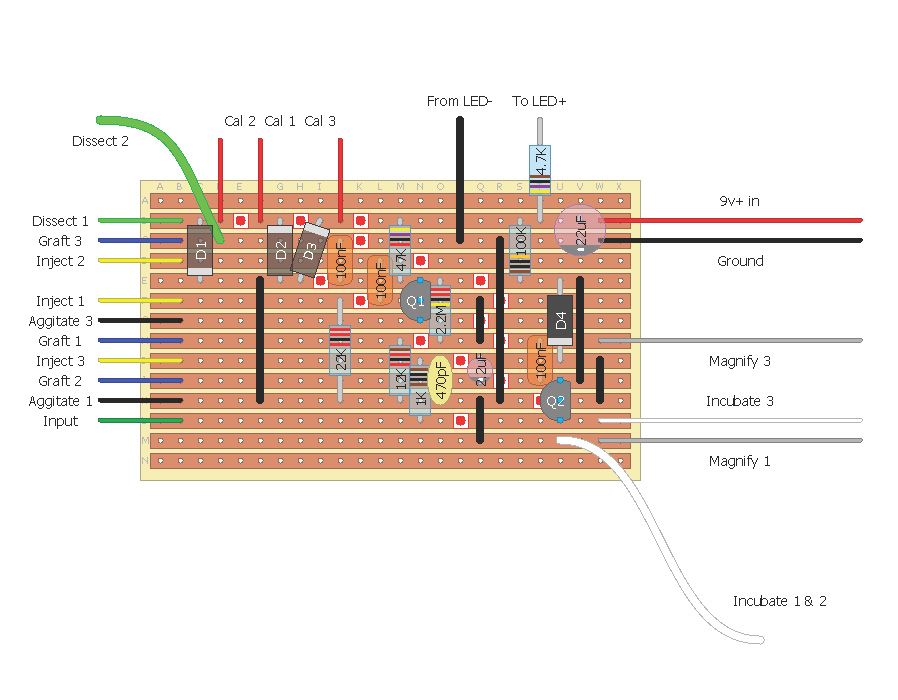
the circuit will work with or without the power filtering cap. these are also called power bypass capacitors. the only difference is less noise when you are not playing the guitar and the amp is cranked. this also depends on your power distribution on your pedal board. a brick with many isolated and regulated outs will likely have this cap placed at the brick before the power entry of the guitar pedal. some builders leave it out for money, laziness, incompetence, intentional shit factor. I left them out when I was starting cause I never saw this stuff in the circuit for a fuzz face or devi-ever so I never knew I would want that. there is a worry that 20 pedals with 100uf will maybe cause an instantaneous rush of current that will put the power supply into some oh shit lets turn myself off mode. this can be fixed by a power cycle since all the 100uf caps are already charged when you power on the pedal board the second time. the value of the power filter cap is not critical. you can have anything from 1nF to 1000uf. realistically though probably a single 100uf or 10uf is fine. some people prefer a combination of poly and electrolytic. you can combine a 100uF in parallel with 10nF. another good one is 10uF with 1nF. the smaller poly cap attenuates high frequency noise better. poly has no hysteresis like ferromagnetic ceramic caps therefor it does not generate harmonics.HighDeaf1080p wrote:So the schematic I stole the LED protection from had a 22uF capacitor before the resistor. Can anyone tell me if the capacitor's value is critical in any way. I only have a 10uF in my hoard at the moment. I'm expecting that the capacitor is only there to ease the speed of on/off...is that correct?

if we add a 100R, 47R, 22R resistor before the caps, we will have a very simple RC low pass filter. the resistor greatly increases the function of the capacitor to reduce power supply noise. it also puts a current limiting resistor between the dirty power rail and the clean power rail. the feature works in both directions. any power noise generated by the guitar pedal will be arrested before it can get into the main 9v power supply to cause problems for other guitar pedals that have no power filtering cap. the diode does nothing here. it only does something when the power is applied backwards. if you can plug in a guitar pedal, you do not need the diode.
I think you are doing more than assuming, I think you read this somewhere, you know the right answer already. you are correct.HighDeaf1080p wrote:I assume the 4.7k resistor is what's actually protecting the LED, and changing the value of that determines how bright or dim the LED is...
WWW.EATYOURGUITAR.COM <---- MY DIY STUFF
-
eatyourguitar
- IAMILFFAMOUS
- Posts: 3127
- Joined: Sun Oct 03, 2010 12:37 pm
- Location: USA, RI
Re: My First Fuzz...
the LED will have instant death at 9v with current limited by the LED and the power supply. I have never seen an LED last more than 1 second on a wall power 9v supply. LED's generate enough heat to cause damage to themselves. every LED has a maximum current that should not be exceeded. you can estimate the diode voltage drop across an LED to be about 1.8v to 2.2v. use 9v - 2v = 7v then use ohms law to get the correct current for a 7v drop across a resistor that has exactly 2ma to 10ma current. whatever you decide.HighDeaf1080p wrote:I was calling it LED protection because, while I don't really care how bright the LED is, I do care about the LED burning out quickly, which I understand will happen if you don't use a resistor or some kind.
WWW.EATYOURGUITAR.COM <---- MY DIY STUFF
-
HighDeaf1080p
- experienced

- Posts: 572
- Joined: Tue Feb 09, 2016 9:26 am
- Location: Denver, CO
Re: My First Fuzz...
Agreed, it was more than "assuming"...I read someone say the the resistor was necessary so it doesn't burn out...and elsewhere I read someone say they used a 300ohm resistor here which makes for a VERY bright LED. 
2+2 and all that jazz.
Thank you for the clean power explanation!!
2+2 and all that jazz.
Thank you for the clean power explanation!!
All the pedals...the jolly, candy-like pedals...
http://www.soundcloud.com/highdeaf1080p
Comey for president 2016, 2020, 2024, etc.
http://www.soundcloud.com/highdeaf1080p
Comey for president 2016, 2020, 2024, etc.
-
HighDeaf1080p
- experienced
- Posts: 572
- Joined: Tue Feb 09, 2016 9:26 am
- Location: Denver, CO
Re: My First Fuzz...
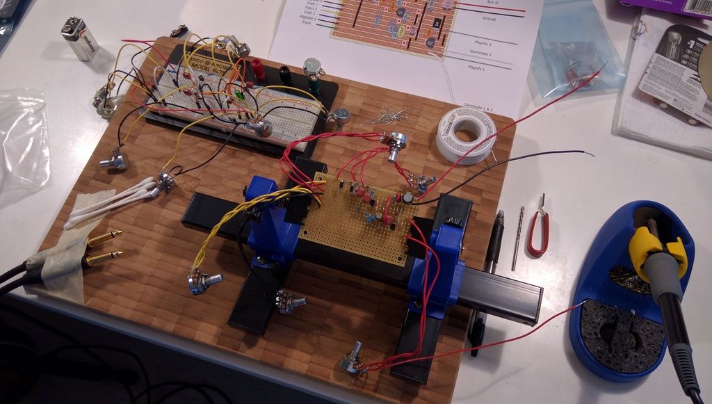
First I made the cuts and tested them with my new better multimeter to make sure I had gotten all the copper cut completely, and there was no continuity.

Then I soldered on the components to match the breadboard (hopefully).
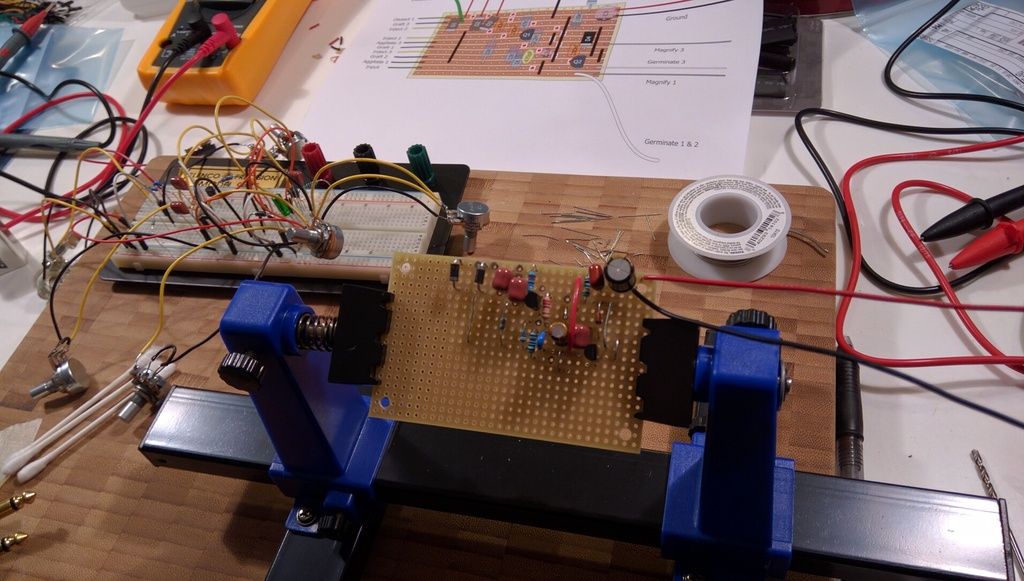
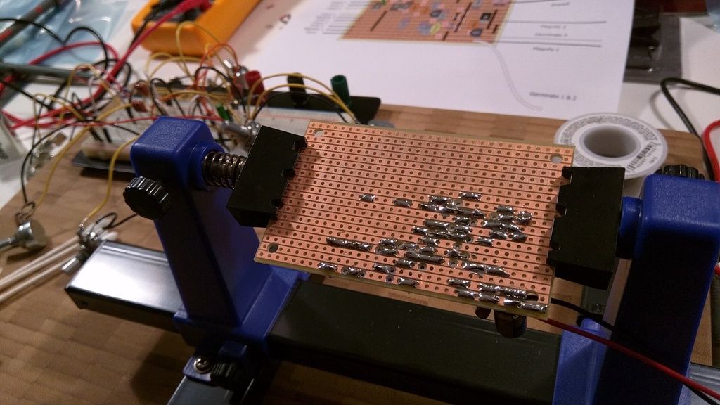
I am a complete retard at soldering. Wow. I sure hope that is something you get better at with practice. Here is the best I could get it, but it seems the solder joints are all good with the continuity tester, and I even discovered one tiny incorrect bridge with the tester and fixed it:
Clearly I didn't need nearly as large of a Vero board. Guess I could have cut it down before hand. ah well, lesson learned. I'm just waiting for the other germanium diode to arrive in the mail. If it doesn't come tomorrow I can at least solder up all the second set of potentiometers and get them connected to the board with plenty of extra length since I don't know how far they'll have to reach in the enclosure I'm having made.

Then I soldered on the components to match the breadboard (hopefully).

I am a complete retard at soldering. Wow. I sure hope that is something you get better at with practice. Here is the best I could get it, but it seems the solder joints are all good with the continuity tester, and I even discovered one tiny incorrect bridge with the tester and fixed it:

Clearly I didn't need nearly as large of a Vero board. Guess I could have cut it down before hand. ah well, lesson learned. I'm just waiting for the other germanium diode to arrive in the mail. If it doesn't come tomorrow I can at least solder up all the second set of potentiometers and get them connected to the board with plenty of extra length since I don't know how far they'll have to reach in the enclosure I'm having made.
All the pedals...the jolly, candy-like pedals...
http://www.soundcloud.com/highdeaf1080p
Comey for president 2016, 2020, 2024, etc.
http://www.soundcloud.com/highdeaf1080p
Comey for president 2016, 2020, 2024, etc.
-
HighDeaf1080p
- experienced
- Posts: 572
- Joined: Tue Feb 09, 2016 9:26 am
- Location: Denver, CO
Re: My First Fuzz...
Oh...and soldering irons are very hot. Don't ask me how I know this.
All the pedals...the jolly, candy-like pedals...
http://www.soundcloud.com/highdeaf1080p
Comey for president 2016, 2020, 2024, etc.
http://www.soundcloud.com/highdeaf1080p
Comey for president 2016, 2020, 2024, etc.
-
HighDeaf1080p
- experienced
- Posts: 572
- Joined: Tue Feb 09, 2016 9:26 am
- Location: Denver, CO
Re: My First Fuzz...
Okay...I have one more pot, and then the input wire to solder on the board tomorrow night, then I can hook it up to the breadboard power and ground buses and test it. I'm so nervous that it will either not work, or not sound like the breadboard does. But, I've tested every connection as I've gone, used a heat sink when soldering any transistors, or diodes, and followed the layout alongside the schematic 10 times. I've done all I can to make sure this works first try. I'll report back tomorrow night. 
EDIT: just caught from looking at the above photo, that I got the germanium diode in backwards. I was being super careful, but I can see now that I got the diode orientation wrong on my vero board layout drawing, and then carefully copied it when soldering...but at least I caught it before firing things up. I need to double check polarity on the caps and diodes, because all previous checks were just following routing to and from components. *sigh* I'll flip that thing around tonight when I add the last pot, and wire. Time I learned to desolder I suppose.

EDIT: just caught from looking at the above photo, that I got the germanium diode in backwards. I was being super careful, but I can see now that I got the diode orientation wrong on my vero board layout drawing, and then carefully copied it when soldering...but at least I caught it before firing things up. I need to double check polarity on the caps and diodes, because all previous checks were just following routing to and from components. *sigh* I'll flip that thing around tonight when I add the last pot, and wire. Time I learned to desolder I suppose.

All the pedals...the jolly, candy-like pedals...
http://www.soundcloud.com/highdeaf1080p
Comey for president 2016, 2020, 2024, etc.
http://www.soundcloud.com/highdeaf1080p
Comey for president 2016, 2020, 2024, etc.
-
HighDeaf1080p
- experienced
- Posts: 572
- Joined: Tue Feb 09, 2016 9:26 am
- Location: Denver, CO
Re: My First Fuzz...
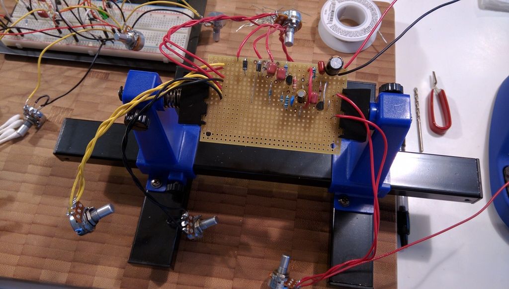
Updated:

All the pedals...the jolly, candy-like pedals...
http://www.soundcloud.com/highdeaf1080p
Comey for president 2016, 2020, 2024, etc.
http://www.soundcloud.com/highdeaf1080p
Comey for president 2016, 2020, 2024, etc.
-
crochambeau
- IAMILF
- Posts: 2220
- Joined: Mon Jul 20, 2015 12:49 pm
- Location: Cascadia
- Contact:
Re: My First Fuzz...
HighDeaf1080p wrote:Oh...and soldering irons are very hot. Don't ask me how I know this.
I like the use of a drill to interrupt the strip, very effective.
I've seen much worse soldering, don't be too hard on yourself in that regard. The thing to keep in mind: when it melts solder flows *to* the heat like water flows downhill, so neat soldering entails wetting the tip of your iron with a little solder then "preheating" the joint by placing the iron tip so it is in thermal contact with both the pad (strip, whatever copper conductor or conductive node you're using) AND the leg/connection point of the component you're placing. The liquid film (wetted tip) of the iron is to provide a solid thermal contact. Once you've established heat (knowing this is simply a matter of practice and doing) feed in the solder to establish the connection.
The entire operation I have described typically takes about a half second. The solder you feed into the joint wants to be heated to the point at which it flows right into the nooks and crannies, again, heat the parts - not the solder. A lot of times the actual inflow of solder will take longer than the half second I describe, but the initial establishment of material feeding into the joint shouldn't take long. I personally feel like something is wrong if I'm at a joint longer than 2 seconds, usually a prep issue.
My method also involves letting the tip of the incoming solder "kiss" the iron at first to accelerate melt, once it goes liquid it takes everything with it - no worries.
Mind you, don't rush, you want to gauge the completeness by the infill of the joint itself and the confirmation of wetted/embedded parts & sides - not by amount of material.
-
HighDeaf1080p
- experienced
- Posts: 572
- Joined: Tue Feb 09, 2016 9:26 am
- Location: Denver, CO
Re: My First Fuzz...
Thank you. Yes, there are a lot of things going on in a very short amount of time, so I guess I can expect some practice to be required.
I've been aiming for "one-mississippi" for heating the copper/component leg, and "two-mississippi" feeding in the solder...but seems something always would go in a way I wasn't happy with and leave me there through "three-mississippi" fiddling with it. It's almost like the solder is disappearing complete as I'm feeding it in, but then when I lift the iron, it all comes back like magic and I'm left with those bulging joints. I think from your description, my problem may be that I'm feeding the solder at the tip of the iron or the joint between the iron and the copper and component leg...instead of kissing the iron tip and then feeding it into the hot component leg to let it flow towards the iron from there.
I think just about every solder joint on that board is a 3 second joint or nearly that long...so I'll keep practicing, trying to get down to two seconds or less.
I have the iron set at 710 degrees...seemed like a logical choice, since I had no idea of a good temp and could find ZERO advice on that with a google search. The consensus seemed to simply be "set the iron at the right temp to achieve what you need to."
The iron seems on the hot side, but I think it's working for me. I like the instantaneous liquifying of the solder, and the piece of mind that the copper and component leg is definitely going to get hot enough to form that bond with the liquid solder. I'm scared to back off the temp and start getting solder joints that aren't bonded with the metal under them, and just a ticking time-bomb. Maybe I worry too much and over-analyze everything. Haha.
All the pedals...the jolly, candy-like pedals...
http://www.soundcloud.com/highdeaf1080p
Comey for president 2016, 2020, 2024, etc.
http://www.soundcloud.com/highdeaf1080p
Comey for president 2016, 2020, 2024, etc.
-
crochambeau
- IAMILF
- Posts: 2220
- Joined: Mon Jul 20, 2015 12:49 pm
- Location: Cascadia
- Contact:
Re: My First Fuzz...
My iron is usually parked around 725 F, I run 63/37. I think "by the book" I'm a touch hot too, but honestly setting it where it works best for you is the key. I've explored lower settings and my dwell time or repeat rate usually climbs, much hotter and I've got to tend the tip more often. It really just boils down to a personal rhythm thing, and different formulas of solder also make their mark. I had to totally adjust myself to the pound of 60/40 I had last summer.
Don't sweat the small stuff though, with the exception of Germanium, most everything these days is pretty heat tolerant. Slapping a heat sink (clips) on the Ge during installation will enable you to go crazy on the heat soak without much risk.
Don't sweat the small stuff though, with the exception of Germanium, most everything these days is pretty heat tolerant. Slapping a heat sink (clips) on the Ge during installation will enable you to go crazy on the heat soak without much risk.
-
HighDeaf1080p
- experienced
- Posts: 572
- Joined: Tue Feb 09, 2016 9:26 am
- Location: Denver, CO
Re: My First Fuzz...
Good! Yes, I'm using 63/37 as well.
Removing and re-installing my germanium diode tonight, I'll definitely get some use out of that heat sink.
Removing and re-installing my germanium diode tonight, I'll definitely get some use out of that heat sink.
All the pedals...the jolly, candy-like pedals...
http://www.soundcloud.com/highdeaf1080p
Comey for president 2016, 2020, 2024, etc.
http://www.soundcloud.com/highdeaf1080p
Comey for president 2016, 2020, 2024, etc.
-
HighDeaf1080p
- experienced
- Posts: 572
- Joined: Tue Feb 09, 2016 9:26 am
- Location: Denver, CO
Re: My First Fuzz...
Well, I finished soldering everything up, and as I feared, it is not the same as the breadboard version. Not sure where it went wrong...it works similarly and has a similar sound (not exact) but I am missing a ton of volume and gain...and one of the pots works backwards for no explainable reason that I can find. It's hooked up the same as the C1k on the breadboard, but this one has max gain to the left and the other has max gain to the right.
Without every knob cranked to max I don't have the same acceptable volume level that the breadboard does...so I can't get any of the more subtle less distorted sounds. When I turn the knobs that are between each transistors emitter and ground, on the breadboard it makes a noise like someone breathing into a microphone, but nothing like that on either of them on the soldered veroboard.
Only obvious difference is the capacitors i put on the 9v+ to filter it. The breadboard doesn't have any. Could that cause the difference in output and gain on some of the pots?
Strange. Can I increase the output volume by reducing the value of the potentiometer at the end of the chain? It's an B100k right now.
All the pedals...the jolly, candy-like pedals...
http://www.soundcloud.com/highdeaf1080p
Comey for president 2016, 2020, 2024, etc.
http://www.soundcloud.com/highdeaf1080p
Comey for president 2016, 2020, 2024, etc.
-
eatyourguitar
- IAMILFFAMOUS
- Posts: 3127
- Joined: Sun Oct 03, 2010 12:37 pm
- Location: USA, RI
Re: My First Fuzz...
Germanium diodes have very weak bonds to the leads and the glass can break. Always remove germanium diodes with hemostat on the leads, not on the glass package. Sometimes they break during assembly. I buy 10 packs of germ diodes on ebay. If a diode breaks, it is the same as no diode.
Breadboard capacitance is like 100pf in parallel to every node combination. That might explain it. The told me i can make a pcb for you in PM so maybe that will sound better than the vero.
Breadboard capacitance is like 100pf in parallel to every node combination. That might explain it. The told me i can make a pcb for you in PM so maybe that will sound better than the vero.
WWW.EATYOURGUITAR.COM <---- MY DIY STUFF