Let's see your finished DIY projects!
Moderator: Ghost Hip
Forum rules
The DIY forum is for personal projects (things that are not for sale, not in production), info sharing, peer to peer assistance. No backdoor spamming (DIY posts that are actually advertisements for your business). No clones of in-production pedals. If you have concerns or questions, feel free to PM admin. Thanks so much!
The DIY forum is for personal projects (things that are not for sale, not in production), info sharing, peer to peer assistance. No backdoor spamming (DIY posts that are actually advertisements for your business). No clones of in-production pedals. If you have concerns or questions, feel free to PM admin. Thanks so much!
-
bortlett
- involved

- Posts: 74
- Joined: Wed Oct 31, 2012 12:12 pm
- Location: Near DC
Re: Let's see your finished DIY projects!
That tremolo is sweet. Tremolo is next on my list, but needless to say, it will not be that rad.
-
eatyourguitar

- IAMILFFAMOUS

- Posts: 3127
- Joined: Sun Oct 03, 2010 12:37 pm
- Location: USA, RI
Re: Let's see your finished DIY projects!
Mike, I'm curious, what kind of wah pot did you use and why?
WWW.EATYOURGUITAR.COM <---- MY DIY STUFF
-
Mike

- committed

- Posts: 467
- Joined: Wed Jun 30, 2010 6:43 pm
- Location: Savannah, GA
- Contact:
Re: Let's see your finished DIY projects!
I used the pot that was originally in the Variwah. I think it is custom made to match the mechanism. It is a dual gang pot, and runs from 0 into the 800K range. It has a huge dead spot at the beginning of the rotation, and a huge plateau at the end of the rotation. Once it moves off of 0, though, it is linear over its range. When setup right, it covers the entire range of the pot, while leaving plenty of wiggle room to keep the pot safe. It looks like Akai used a trimpot to set the taper.
I am using both halves of the pot. One half is left linear, and one half has a trimpot to adjust the taper. The linear half of the pot controls the wave distort ("shift") when the toggle switch is down, leaving either the top center knob or the tap tempo to set speed. The tapered half of the pot controls the speed when the toggle switch is up, leaving the top center knob to handle wave distort. If I didn't do it like this, all of the fastest speeds were bunched up in the last 10% of rotation. This way, it spreads the fast speeds out over a more useful range, but the treadle still works as expected when controlling wave distort.
I don't get the full range of the LFO with the pot, but I get pretty close. I think it covered something like 0.15V - 4.97V. I lose a small amount of the slowest speeds.
If you were to do this in a regular wah enclosure controlling speed only, I would think a standard wah pot would work well.
Mike
My diy pedal blog: Just one more build...
-
karmablock

- experienced

- Posts: 780
- Joined: Mon Nov 23, 2009 1:47 am
- Location: Austin, Texas
Re: Let's see your finished DIY projects!
How did you set up the rotary switches?
-
Mike
- committed
- Posts: 467
- Joined: Wed Jun 30, 2010 6:43 pm
- Location: Savannah, GA
- Contact:
Re: Let's see your finished DIY projects!
Waveform is a 1P8T. Multiplier is 2P6T, but you only use one pole. Basically, you make a string of resistors that act as a big voltage divider, and tap off of them for the control voltage.
I made this a couple of years ago to show someone how to setup the waveform rotary, and about what you can expect for the voltages: http://imageshack.us/a/img411/5316/tttr ... ltages.jpg
The resistor values aren't that important, but the ratios are. The two resistors on the end need to be half the value of the resistors in the middle.
For the multiplier, there are six options instead of eight, so you only use the bottom five taps off the resistors. You could combine the top three resistors into one: 5V--[25K]--[10k]--[10k]--[10k]--[10k]--[10k]--[5k]--GND
Mike
My diy pedal blog: Just one more build...
-
Bret608
- committed

- Posts: 115
- Joined: Thu Jun 03, 2010 4:07 pm
- Location: Madison, Wisconsin
Re: Let's see your finished DIY projects!
I always like sharing here, even if my builds aren't too exciting in the wake of all the awesomeness! This is a Distortion + built on Culturejam's Plus-Dist board. For the diodes, I did one clear glass 1n270 on one side and two black and blue 1n270s in series on the other. It's a pretty awesome assymetrical setup. It gets me those Bob Mould sounds, and that was the goal.

Uploaded with ImageShack.us

Uploaded with ImageShack.us

Uploaded with ImageShack.us

Uploaded with ImageShack.us
-
Bellyheart

- IAMILFFAMOUS
- Posts: 5791
- Joined: Mon Nov 10, 2008 11:23 pm
- Location: Richmond, Va
Re: Let's see your finished DIY projects!
Does he still sell pcbs?
-
ran_dizolph

- involved
- Posts: 52
- Joined: Sat Oct 20, 2012 11:47 am
Re: Let's see your finished DIY projects!
Finished up my 3rd build last night! No gut shots, but the wiring is getting a bit better. Put a slightly bigger output cap on it, and it sounds awesome!

-
Bret608
- committed
- Posts: 115
- Joined: Thu Jun 03, 2010 4:07 pm
- Location: Madison, Wisconsin
Re: Let's see your finished DIY projects!
This was a run that he did last summer, so I'm not sure. I'd just check in the Buy-Sell-Trade section over at BYOC, or even just PM him. Someone over at Madbean had a a red version of the board, so I suspect there was another run at some point.Bellyheart wrote:Does he still sell pcbs?
-
LaoWiz

- Supporter

- Posts: 2035
- Joined: Wed Apr 14, 2010 4:03 pm
Re: Let's see your finished DIY projects!
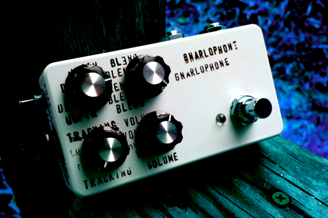
Dude, you must have a fucking clip. Destroy switch, wtf. And tap temp trem. Badass looking box. Must sound apeshit!skullservant wrote:Posted them in the Dirge Cave, but I figured I would here as well:
FY-2 + DESTROY SWITCH -> TAP TEMPO TREM.
DAN IS AN ETCHING WIZARD.


Most active on Instagram
Mo Destinations:
Laowiz Big Cartel
Reverb Shop
Ebay Shop for Vintage Parts, Test Equipment, vintage radios
Shark Tank
Build Archive
Mo Destinations:
Laowiz Big Cartel
Reverb Shop
Ebay Shop for Vintage Parts, Test Equipment, vintage radios
Shark Tank
Build Archive
-
skullservant

- IAMILFFAMOUS
- Posts: 16575
- Joined: Wed Dec 28, 2011 12:55 am
Re: Let's see your finished DIY projects!
I don't have a clip, I finished it WAY too late to record anything and boxed it up after I tested it 
Mathias should defintely do a demo!!!!! The destroy switch is a bend on the FY-2 that gives it about a 100% volume bump AND make it sound like it's stacked with a Big Muff!
Mathias should defintely do a demo!!!!! The destroy switch is a bend on the FY-2 that gives it about a 100% volume bump AND make it sound like it's stacked with a Big Muff!
-
LaoWiz
- Supporter
- Posts: 2035
- Joined: Wed Apr 14, 2010 4:03 pm
Re: Let's see your finished DIY projects!
Damn, what you do bypass the mid scoop filter?skullservant wrote:I don't have a clip, I finished it WAY too late to record anything and boxed it up after I tested it
Mathias should defintely do a demo!!!!! The destroy switch is a bend on the FY-2 that gives it about a 100% volume bump AND make it sound like it's stacked with a Big Muff!
Most active on Instagram
Mo Destinations:
Laowiz Big Cartel
Reverb Shop
Ebay Shop for Vintage Parts, Test Equipment, vintage radios
Shark Tank
Build Archive
Mo Destinations:
Laowiz Big Cartel
Reverb Shop
Ebay Shop for Vintage Parts, Test Equipment, vintage radios
Shark Tank
Build Archive
-
skullservant
- IAMILFFAMOUS
- Posts: 16575
- Joined: Wed Dec 28, 2011 12:55 am
Re: Let's see your finished DIY projects!
Connected two points together until it sounded good  hahahaha
-
Officer Bukowski
- IAMILFFAMOUS
- Posts: 3307
- Joined: Wed Nov 17, 2010 9:13 pm
Re: Let's see your finished DIY projects!
clari(not) clone w/ fuzz on/off switch

I make pedals. SHARK TANK
-
Chankgeez

- IAMILFFAMOUS
- Posts: 42283
- Joined: Tue Oct 11, 2011 1:40 am
- Location: https://www.youtube.com/watch?v=FGhbeHujNZQ youtube.com/watch?v=V-2l7kkBURc
Re: Let's see your finished DIY projects!
Get ready to get sued by Doug. Almost looks better than the real thing.Officer Bukowski wrote:clari(not) clone w/ fuzz on/off switch
…...........................…psychic vampire. wrote:The important take away from this thread: Taoism and Ring Modulators go together?
Sweet dealin's: here
"Now, of course, Strega is not a Minimoog… and I am not Sun Ra" - dude from MAKENOISE
#GreenRinger