eatyourguitar wrote:building it on vero, and dropping it, and I don't know how much experience you have, I would say maybe it would be good to build another one but this time clean the copper with scotchbrite before you do anything and then finish soldering in less than 24 hours to avoid oxide build up. I would even clean with alcohol again before soldering. watch the these videos. only difference is that you use scotchbrite instead of the rubber eraser in the video.
http://www.amazon.com/Scotch-Brite-Heav ... 003FYJ83S/[youtube]http://www.youtube.com/watch?v=AY5M-lGxvzo[/youtube]
[youtube]http://www.youtube.com/watch?v=VgcPxdnjwt4[/youtube]
Wow thanks eatyourguitar - that video on soldering was really interesting - I didn't know you were supposed to clean surfaces before soldering them. Scotchbrite is not something I've encountered before; I looked at their website and they seem to have at least 20 products that clean surfaces in the way you are mentioning - do you mean with a liquid cleaner (possibly alcohol based) or a scouring product like a pad? Any hints would be great before I buy the wrong thing and destroy whatever board I'm working on. I'm based in the UK and I'm not sure how much of this stuff is available over here, but I'm sure Amazon or Ebay will have it somewhere! Regarding the time spent - the board was populated in about an hour, but then because work has been horrible this year, the board sat in a box for four months before I got a chance to attach cables and knobs, jacks, power etc.
The second video about DIP chips - I use DIP sockets for these, I didn't realise that I need to check the solder falls through the hole from the solder side of the board to the upper (component) side... I'm going to have to check a non functioning tremolo build now, perhaps that's what is keeping it from flashing an LED. It looks like I also need a thinner soldering iron tip... I think I'll watch the rest of that series!
My previous experience is limited to say the least - I don't have a background in electrical engineering (or anything practical or musical for that matter), and I find this stuff quite complex but fascinating, so I hope eventually things will sink in more. Most of my builds work first time (when I follow the layout and don't change anything - the exception being tremolos which seem to hate me) but the creative part of me wants to fiddle with things and alter them to create new sounds, and that's where a lack of technical knowledge/electrical theory causes issues...
crochambeau wrote:
So, if I am reading this correctly: the pedal, when operated by itself, still works. True?
True - it's a crazy thing

crochambeau wrote:Few questions:
When you are playing the pedal by itself, and it is working, what exactly is your signal path? I know, I know = guitar or bass into pedal into amp - name names, or better yet, break out the multimeter and measure stuff like DC resistance on the amp input, DC resistance on the instrument output. Keep notes - I don't need to know this shit..
Guitar was a Yamaha RGX110 into the pedal via a 10foot / 3m cable, then a 2 foot / 60cm cable to the amplifier which is an Ampeg BA-108 (bass amplifier, solid state). The Bass guitar was a Harley Benton Short Scale passive bass. I've also tried a Cort G100 guitar in the same combination of pedal/cable/ amplifier.
How do you measure DC resistance on the amp input? When the cable is plugged in there's no way I can get the probe from my DMM into the socket?
crochambeau wrote:Now, when you add pedals, presumably starting with one: what changes? Again, you want to draw a road map of input/output characters and observe the changes in relation to the measurements.
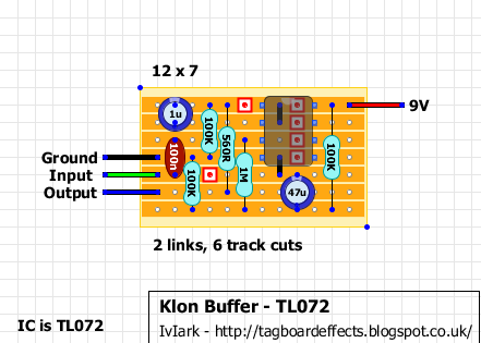
It might behoove you to build a unity gain buffer or two to "isolate" the effect to a degree. But ultimately, this is a matter of test & observation.
Here are my thoughts: it is possible the feedback path, while it operates in a satisfactory manner locally (in the three piece straight line set-up), may react in a completely different manner when exposed to other active stages, be it the output of an effect or a different type of input load (I have observed, at times, startling performance changes when I take an experimental circuit off my bench (the bench amp has a MOSFET input and is really high impedance) and plugged into an old tube amp that reflects a 100K load.
I think the above questions are best answered below your next quote thanks:
crochambeau wrote:So, think about where the feedback path is, and consider this might be a situation made for an onboard buffer (TL072 style). I say might, it's hard to say. I have some stuff that will essentially do a filter sweep as I roll down my guitar volume due to the tuned circuit of inductor (pup) + cap (input DC blocker) + resistor (volume control) that a buffer would kill. This is why I mention an external buffer you can move around and play with before committing to the change.
Also, EYG poses a really good point in that it would be a good idea to replicate the circuit, taking care with assembly. That way you have a spare, or something to sling and a whole 'nother round of the best education.
OK you said buffer and I thought I wondered if I have any pedals with buffers in them; step forward the Boss BF2 Flanger in its purple glory and I plugged the guitar into the Boss pedal, then a cable from that to the Fuzz, and from the fuzz to the amplifier. I made them both use the same power supply and voilà, success! The feedback control now oscillates and causes damage (albeit less than before, but that's OK) and the pedal works and can even be plugged into other pedals with success

And flanger into fuzz is always a good sound in my opinion. It seems I need to build a buffer - I looked for TL072 buffers and found this:
Does that look like a possible circuit to try? I've got all the parts for this already, but I might not get a chance to make it until next weekend. I think I'll want it on a footswitch so I can turn it off for extreme chaos if the pedal isn't plugged into anything else

Thanks to both of you for your patience
