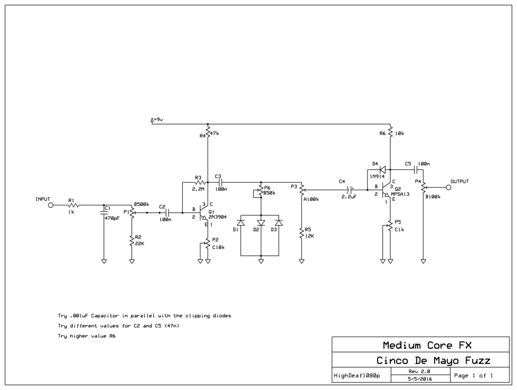
Great points.Nocentelli wrote:R2 seems pointless since you already have a pull down resistor formed by the 500k input level pot, all it will do is slightly reduce the input impedance and alter the taper and value of that pot. R6 should be much lower (e.g. 10k) if you use a Darlington like the MPSA13 (it's only 100k for the first version bazz fuss that used a standard npn transistor like a 2N3904) but you can try higher to see if you can hear a difference.
My First Fuzz...
Moderator: Ghost Hip
Forum rules
The DIY forum is for personal projects (things that are not for sale, not in production), info sharing, peer to peer assistance. No backdoor spamming (DIY posts that are actually advertisements for your business). No clones of in-production pedals. If you have concerns or questions, feel free to PM admin. Thanks so much!
The DIY forum is for personal projects (things that are not for sale, not in production), info sharing, peer to peer assistance. No backdoor spamming (DIY posts that are actually advertisements for your business). No clones of in-production pedals. If you have concerns or questions, feel free to PM admin. Thanks so much!
-
culturejam

- Supporter

- Posts: 2381
- Joined: Sun Jun 28, 2009 5:25 pm
- Location: Nueva Yersey
Re: My First Fuzz...
Disclaimer #1: Co-Founder, Product Developer at Function f(x).
-
HighDeaf1080p
- experienced

- Posts: 572
- Joined: Tue Feb 09, 2016 9:26 am
- Location: Denver, CO
Re: My First Fuzz...
Egads, you guys have got me so excited to start trying stuff!! Parts were all shipped, so should be here tomorrow or Saturday. I'll need to find a good source here in town for one-off changes of value and stuff, like that 100k vs 10k resistor.
I'll keep everyone appraised of how it develops.
I'll keep everyone appraised of how it develops.
All the pedals...the jolly, candy-like pedals...
http://www.soundcloud.com/highdeaf1080p
Comey for president 2016, 2020, 2024, etc.
http://www.soundcloud.com/highdeaf1080p
Comey for president 2016, 2020, 2024, etc.
-
HighDeaf1080p
- experienced
- Posts: 572
- Joined: Tue Feb 09, 2016 9:26 am
- Location: Denver, CO
Re: My First Fuzz...
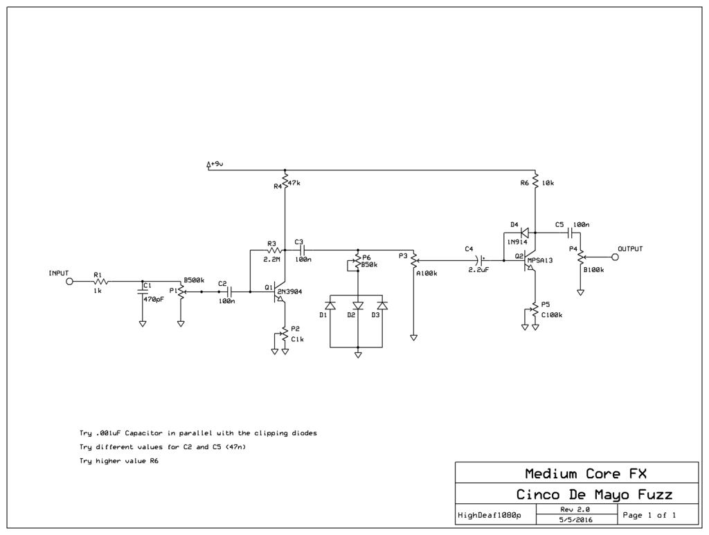
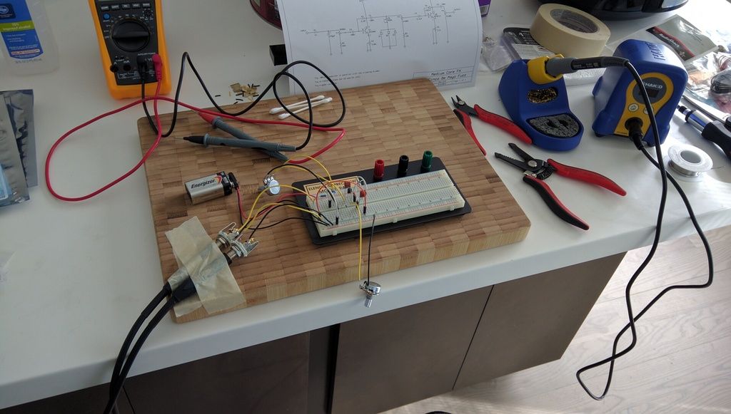
Here's what I'm going to breadboard with once the parts arrive this weekend.
I will edit this as changes occur on breadboard, and I will update this thread with progress, and if worthy...sound clips.
I decided to place the clipping diodes (whatever they end up being) on a pot, so I can remove clipping entirely, or run it all the way to max...and I put a gain control on the MPSA13 as well. I figure any of these that don't have a dramatic effect can always be taken back out before final schematic is done. Not sure on the values of pots, and I'm wondering if I need some polarity protection on the input 9V+.
I really appreciate everyone's help getting me to this point!!

All the pedals...the jolly, candy-like pedals...
http://www.soundcloud.com/highdeaf1080p
Comey for president 2016, 2020, 2024, etc.
http://www.soundcloud.com/highdeaf1080p
Comey for president 2016, 2020, 2024, etc.
-
crochambeau

- IAMILF

- Posts: 2220
- Joined: Mon Jul 20, 2015 12:49 pm
- Location: Cascadia
- Contact:
Re: My First Fuzz...
Looking forward to it!
In the event you find yourself continuing to enjoy the process, it might be a good idea to pick up one of those resistor/capacitor assortments so you have a range of parts you can experiment with.
P5 looks a touch large to me.
In the event you find yourself continuing to enjoy the process, it might be a good idea to pick up one of those resistor/capacitor assortments so you have a range of parts you can experiment with.
P5 looks a touch large to me.
-
HighDeaf1080p
- experienced
- Posts: 572
- Joined: Tue Feb 09, 2016 9:26 am
- Location: Denver, CO
Re: My First Fuzz...
I'm having crazy thoughts like trying to put the third clipping diode on a pot so I can transition from symmetrical clipping to asymmetrical clipping with the turn of a knob. The problem with all these crazy schemes is, of course, ending up with a pedal that has 75 knobs on it.
Great suggestion on getting one of those suitcases full of resistors/capacitors/diodes, etc. Let the mad scientist come out.
Great suggestion on getting one of those suitcases full of resistors/capacitors/diodes, etc. Let the mad scientist come out.
All the pedals...the jolly, candy-like pedals...
http://www.soundcloud.com/highdeaf1080p
Comey for president 2016, 2020, 2024, etc.
http://www.soundcloud.com/highdeaf1080p
Comey for president 2016, 2020, 2024, etc.
-
crochambeau
- IAMILF
- Posts: 2220
- Joined: Mon Jul 20, 2015 12:49 pm
- Location: Cascadia
- Contact:
Re: My First Fuzz...
That's why you work out the crazy schemes before you cut metal, only keeping the most hyperactive of functions, everything else is just "voicing" the circuit.HighDeaf1080p wrote:I'm having crazy thoughts like trying to put the third clipping diode on a pot so I can transition from symmetrical clipping to asymmetrical clipping with the turn of a knob. The problem with all these crazy schemes is, of course, ending up with a pedal that has 75 knobs on it.
-
HighDeaf1080p
- experienced
- Posts: 572
- Joined: Tue Feb 09, 2016 9:26 am
- Location: Denver, CO
Re: My First Fuzz...
Good point...Yea, maybe a suitcase full of trim pots would be a good thing to have too. Voice the circuit...remove the trim pot...measure the resistance...replace with a fixed resistor of that value or closest.
All the pedals...the jolly, candy-like pedals...
http://www.soundcloud.com/highdeaf1080p
Comey for president 2016, 2020, 2024, etc.
http://www.soundcloud.com/highdeaf1080p
Comey for president 2016, 2020, 2024, etc.
-
eatyourguitar

- IAMILFFAMOUS

- Posts: 3127
- Joined: Sun Oct 03, 2010 12:37 pm
- Location: USA, RI
Re: My First Fuzz...
some of it can be sorted as power stuff and stability stuff. anything that can be removed with no affect should be removed. the redundant pulldown resistor at the input was a good example, we found that the 500K pot was sufficient. having a control for diode clipping can be implemented a few different ways but after you have built and tested them all you will be a bit more straight forward in a clipping control that has a useful range throughout the pot with no unnecessary parts. most people do it with a volume control before the diode clipping section but you can also vary the signal impedance immediately before the diode and therefor the clipping path impedance to ground through the diode. another way is to place the pot in series with the diode to ground. before or after it does not matter. reference Kirchhoff's current law as to why any two resistors (or a diode and a resistor behaving like two resistors at a moment in time) placed in series will always have the same amount of current flowing through each of them. what goes in must come out the other side. it has no where to go. nothing is storing energy. these are resistors. no complicated functions over time need to be calculated. only DC resistance best guess as to your diode shunt current limiting pot and how it fights the impedance of the next input.
WWW.EATYOURGUITAR.COM <---- MY DIY STUFF
-
HighDeaf1080p
- experienced
- Posts: 572
- Joined: Tue Feb 09, 2016 9:26 am
- Location: Denver, CO
Re: My First Fuzz...
Hmm...maybe a switch instead of a pot to bring that third clipping diode in or out of the circuit, allowing a choice between symmetrical and asymmetrical clipping...
And then the pot to control the whole clipping section like I have shown.
I assume I can use a large linear taper pot as a test, and then when I find where in the knob's rotation the effect stops changing dramatically, I can measure the resistance of the pot at that setting and then get a pot that size?
Hopefully that made sense, cuz it sure made more sense in my head that when I read what I wrote.
All the pedals...the jolly, candy-like pedals...
http://www.soundcloud.com/highdeaf1080p
Comey for president 2016, 2020, 2024, etc.
http://www.soundcloud.com/highdeaf1080p
Comey for president 2016, 2020, 2024, etc.
-
eatyourguitar
- IAMILFFAMOUS
- Posts: 3127
- Joined: Sun Oct 03, 2010 12:37 pm
- Location: USA, RI
Re: My First Fuzz...
you are exactly correct. you are smart and creative, I think you have what it takes to wield the iron. later come back after you do it, I will show you how to replace the pot with a A or C taper to finish sorting it out. you can attach all the diodes to one pot on the ground side or the signal side if you want to. diodes are cheap, you can just break glass in half with cutters then solder a new one on top to put it back. this is how I do my testing of prototypes very quickly, always disconnect power from the pedal when soldering with your ESD safe (grounded) iron. if using butane you can fly right through the prototyping this way. it helps to have all the possible configurations for clipping diodes already rehearsed in your head in both schematic, and theory of function. you can design and build in this way until it sounds like something you want or need.HighDeaf1080p wrote:Hmm...maybe a switch instead of a pot to bring that third clipping diode in or out of the circuit, allowing a choice between symmetrical and asymmetrical clipping...
And then the pot to control the whole clipping section like I have shown.
I assume I can use a large linear taper pot as a test, and then when I find where in the knob's rotation the effect stops changing dramatically, I can measure the resistance of the pot at that setting and then get a pot that size?
Hopefully that made sense, cuz it sure made more sense in my head that when I read what I wrote.
WWW.EATYOURGUITAR.COM <---- MY DIY STUFF
-
culturejam
- Supporter
- Posts: 2381
- Joined: Sun Jun 28, 2009 5:25 pm
- Location: Nueva Yersey
Re: My First Fuzz...
I don't think Q2 will bias correctly with a 100K pot acting as the emitter resistor. Like Q1, try 1K or 2K for the pot.
Disclaimer #1: Co-Founder, Product Developer at Function f(x).
-
HighDeaf1080p
- experienced
- Posts: 572
- Joined: Tue Feb 09, 2016 9:26 am
- Location: Denver, CO
Re: My First Fuzz...
Ah, ok. I think I'll try 1K for that one at Q2, and 10K for the emitter on Q1, and see where I end up, since I only have 1 pot that's 1K currently. Then if I have to order another 1k I can at that point.
My multimeter arrives today, which was the last of the items I have been waiting for, and can start working on this beast! Woot!
Since I'm just getting going, maybe its overkill, but I want to test/measure each component with the multimeter before even sticking it in the breadboard. I don't need some faulty component sending me on wild goose chases while I'm just trying to learn and understand how circuits work.

All the pedals...the jolly, candy-like pedals...
http://www.soundcloud.com/highdeaf1080p
Comey for president 2016, 2020, 2024, etc.
http://www.soundcloud.com/highdeaf1080p
Comey for president 2016, 2020, 2024, etc.
-
eatyourguitar
- IAMILFFAMOUS
- Posts: 3127
- Joined: Sun Oct 03, 2010 12:37 pm
- Location: USA, RI
Re: My First Fuzz...
the meter won't test the transistors and those are the only ones that are fragile if powered by the wrong pins with no current limiting resistor. don't put your small signal diodes directly across the power supply with no resistor. resistors and caps will not die. just use the meter to measure resistance of a pot or resistor and then switch it over to check voltages in different places. disconnect the power supply when checking resistance in-circuit. the meter has an internal power supply when testing resistance. only one at a time.
WWW.EATYOURGUITAR.COM <---- MY DIY STUFF
-
HighDeaf1080p
- experienced
- Posts: 572
- Joined: Tue Feb 09, 2016 9:26 am
- Location: Denver, CO
Re: My First Fuzz...
For other extreme beginners who might read this trying to learn, I wanted to outline what I understand so far from laying out, and editing this circuit...and LOTS of reading/research. Since I didn't find any of this conveniently in one place, I hope this can be helpful for someone jumping in. If any of this is wrong, or needs clarification, pros feel free to chime in and correct me:
R1 is there to attenuate the input signal (?)
C1 acts as a Low Pass Filter, taking out unwanted highs (hiss and noise?) from the signal.
P1 acts as a pulldown resistor, which allows any built up current that may leak through C2 to dissipate to ground (through R2), and not cause a "POP" when the pedal is turned on and off. P1 also controls the level of the input signal hitting Q1.
R2 is there to limit the lower end of P1's range...preventing you from being able to completely eliminate the signal going through to Q1.
C2 acts as a High Pass Filter, and, with the help of C3, it isolates the DC to the area around Q1.
Q1 amplifies the input signal, so much so that it distorts.
R4 regulates DC coming in from the battery or 9v jack to power Q1.
R3 mixes some DC current coming in through R4 into the pre-transistor input signal. (I don't fully understand why this is done yet)
P2 regulates DC from Q1 to ground...allowing less to flow to ground increases the gain of Q1 (increasing distortion...remember as the resistor value goes down, the resistance goes up. 1 ohm gives much higher distortion than 1000 ohms.)
C3 then removes the DC from the (now distorted) audio signal.
P6 controls the amount of the audio signal allowed to flow to ground through the clipping diodes D1, D2, and D3, hopefully increasing or decreasing their audible effect.
P3 controls how much of this newly distorted and clipped signal then hits Q2.
R5 limits the amount that P3 can dump signal to ground.
We then play the whole game again, in the next stage:
C4 acting (I assume) as another high pass filter, and block for DC voltage to keep it around the area of Q2. Because its a polarized electrolitic (why?) capacitor, the positive leg is turned to face the incoming positive voltage at Q2.
Q2 again amplifying and distorting the already distorted and clipped audio signal.
R6 regulating DC power coming in from the battery to power Q2.
D4 allowing a LOT of DC into the pre-transistor signal in a one way only flow.
P5 regulating how much DC flows from Q1 to ground and therefore increases/decreases the gain of Q2.
C5 filtering back out the DC from the audio signal.
P4 acting as a simple volume control of the fully amplified/distorted/clipped/re-distorted signal, determining how much is sent to ground and how much is sent to output.
Hopefully that is correct and easy to understand for a total beginner who might read this and follow along with my developing schematic. One thing I don't fully understand is the mixing of DC into the pre-transistor signals. I get that DC must be sent to the transistor's collector to power it and allow amplification. Do the transistors also require some DC on the base in order to be powered or is there another reason?
All the pedals...the jolly, candy-like pedals...
http://www.soundcloud.com/highdeaf1080p
Comey for president 2016, 2020, 2024, etc.
http://www.soundcloud.com/highdeaf1080p
Comey for president 2016, 2020, 2024, etc.
-
HighDeaf1080p
- experienced
- Posts: 572
- Joined: Tue Feb 09, 2016 9:26 am
- Location: Denver, CO
Re: My First Fuzz...
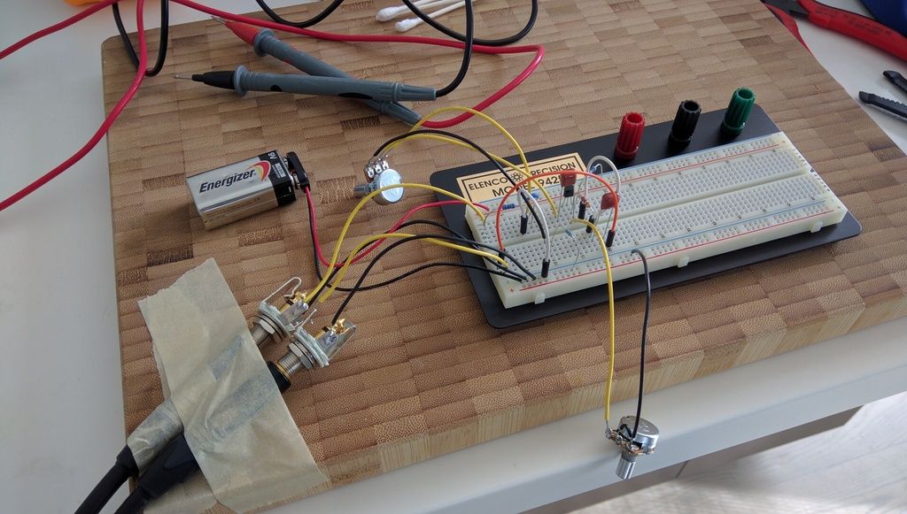
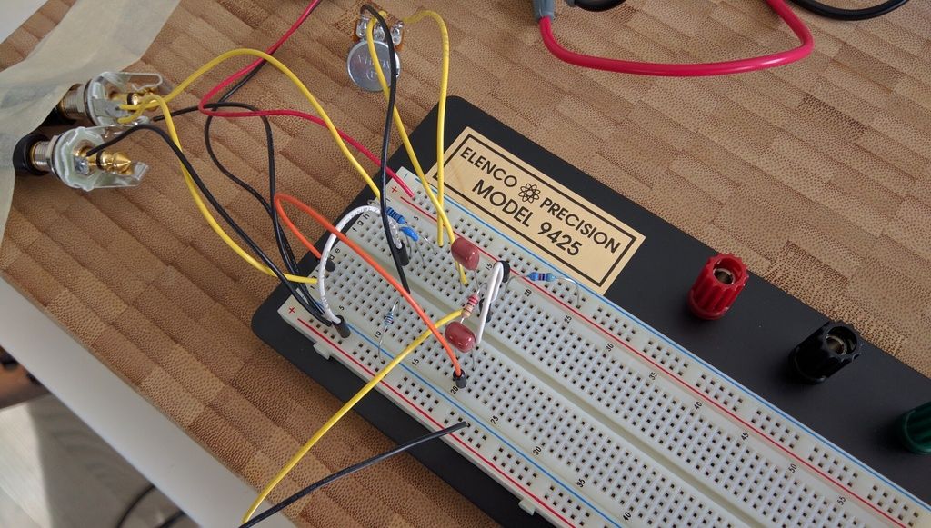
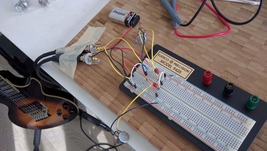
Oh man!!! Ok, so I've got the first half, the elektra distortion part on the breadboard, and fired up. It sounds SOOO good already. And I haven't even auditioned any other transistors, or values for capacitors and pots.
The 2N3904 is pretty low gain it seems. I measured it at HFe: 185 on my multimeter, but I don't know how reliable that is. Unless both the input "attack" knob, and the "gain" knob between Q1's emitter and ground are pretty well cranked, everything stays pretty clean. I realize that will likely change when I get the second stage on there behind it, but I have a feeling we're gonna need to bump up that transistor, at the least, and maybe change some of the resistor values. So far the range seems good on the input and output capacitors, but that also may change as parts change and the second stage goes on.
Only major problem I'm having is that I can't seem to get this multimeter's continuity function to work...or I don't understand how to work it. One of the two. I can barely get it to beep when I hold the leads together. When I touch them to different parts of this working circuit, I get nothing at all. Gonna have to investigate that...but otherwise things are going great.


All the pedals...the jolly, candy-like pedals...
http://www.soundcloud.com/highdeaf1080p
Comey for president 2016, 2020, 2024, etc.
http://www.soundcloud.com/highdeaf1080p
Comey for president 2016, 2020, 2024, etc.