Weird question about Starve knobs

Do-it-yourself pedal building

Moderator: Ghost Hip

Forum rules
The DIY forum is for personal projects (things that are not for sale, not in production), info sharing, peer to peer assistance. No backdoor spamming (DIY posts that are actually advertisements for your business). No clones of in-production pedals. If you have concerns or questions, feel free to PM admin. Thanks so much!
User avatar
moid
experienced
experienced
Posts: 715
Joined: Sun May 03, 2015 6:35 pm
Contact:

Re: Weird question about Starve knobs

Post by moid »

I've drawn your picture in Diylc - I think I've followed it correctly - some of the capicators are electrolytic and I think I've got them the right way round.
Image

Off to build and test this :)
User avatar
crochambeau
IAMILF
IAMILF
Posts: 2204
Joined: Mon Jul 20, 2015 12:49 pm
Location: Cascadia
Contact:

Re: Weird question about Starve knobs

Post by crochambeau »

Please don't hate me if it doesn't work! hahaha

:idk:

Good luck!
User avatar
moid
experienced
experienced
Posts: 715
Joined: Sun May 03, 2015 6:35 pm
Contact:

Re: Weird question about Starve knobs

Post by moid »

I'm not hating you; thanks for your help!

OK I built this today and tried it - I needed to swap the voltage in and out positions around (which seemed odd, but if I kept them as shown above my DMM registered 9 volts going to the fuzz circuit all the time , no matter what I did to the potentiometer). With the voltage swapped the DMM showed that power going to the board went from 9 volts to a few millivolts, and this did indeed cause the pedal to make decaying, random noises.... but the chronic background oscillation is still present, although much more bass like as a very loud rumble rather than the high pitched tones when I used the 100K lin pot. One difference is that with the 100K lin pot letting full power go to the fuzz there is no oscillation; this only occurs as the power is reduced, whereas with the current 10k log pot (yes I have the wrong pot alas) the rumble is constant at all levels of voltage. The problem is almost certainly caused by me not having a 1K pot as you suggested to try... I thought I had a bag of them, but in my enthusiasm I had mistaken 10K log for 1K lin... so perhaps the problem is caused by the 10K Log? Your circuit is definitely lowering the power to the fuzz; so that works and so I'm guessing the loud rumble is caused by me not havng the right pot... any ideas? If the pot is the most likely culprit I'll try to get to a shop near me at the weekend to get the right pot.

Thanks very much for your help so far; I hope your own pedal creation endeavours go well for you!
User avatar
crochambeau
IAMILF
IAMILF
Posts: 2204
Joined: Mon Jul 20, 2015 12:49 pm
Location: Cascadia
Contact:

Re: Weird question about Starve knobs

Post by crochambeau »

The oscillation might be a side effect of starving power. Though...

You say the oscillation persists now, even at a measured 9 volts whereas it did not before (at the same voltage, right?).

If you're getting a range of voltage from the circuit, the variation pot is probably NOT the culprit, though swapping input/output is a question mark.. very well could be that I botched the layout. I'll try to throw something together on strip in the next couple days to see what I can come up with (it might oust the LM regulator for a general purpose transistor), in the mean time, I'd be curious if the circuit behaves correctly when the starve is completely bypassed.

Thanks for the kind words! The burn in effect does resemble Raku to a degree.
User avatar
moid
experienced
experienced
Posts: 715
Joined: Sun May 03, 2015 6:35 pm
Contact:

Re: Weird question about Starve knobs

Post by moid »

OK apologies are in order - I tried the circuit today without a starve pot, just voltage direct to the board from the DC jack and it emits constant crackling buzz / oscillations (although different sounding to what I heard when using your power filtering circuit). I drew the vero layout with hte starve function in place and never thought to try the circuit without a starve knob... anyway, in other newsI found a 1Klin pot on a broken tremolo build I gave up on a year ago and swapped that into the starve position. This stil emits loads of crackling constantly when the guitar is not playing, but doesn't oscillate much at all so is a major improvement over the 100K lin and hte 10K Log pots. I noticed that I can remove the crachle noise if I palm mute the strings after playing them - the pedal goes silent for about 2 seconds then slowly fades the noise crackle in... weird eh? I can remove the noise by lowering the guitar volume knob to almost zero (can't hear guitar either!) but this shows the issue is the pedal amplifying noise too much, all the time. So my guess is it needs some sort of noise gate or volume gate between the circuit and the incoming signal from the audio jack... if I could stretch your patience a little further, would you know of something that would cut incoming audio once it drops below a certain level? I know that some capacitors can do that for certain frequencies (I think) but I can't find anything online (beyond buying a noise gate pedal) that would cut out he unwanted sound and leave just the guitar. Thanks for your thoughts, I'll add your circuit to my pedal definitely, it's much better than the direct current without the regulator! (even with the starve turned to 9 volts!)

I had to use a 220ohm resistor instead of a 200ohm resistor in your circuit; I doubt that would matter much though. You also mentioend trying a 500ohm lin potentiometer instead of the 1K - would you expect that to help the noise level? I suspect this is not connected myself, but thought I'd ask anyway.

Thanks again :)

forgot to mention I placed all the electrolytic capacitors in your circuit so that the long (positive) leg of the capacitor was facing away from the ground strip because that was how I interpreted your drawing (the straight large horizontal line on the capacitor symbol above the smaller horizontal or curved line). If that is wrong, perhaps that would confuse the voltage in and out?
User avatar
moid
experienced
experienced
Posts: 715
Joined: Sun May 03, 2015 6:35 pm
Contact:

Re: Weird question about Starve knobs

Post by moid »

Another apology - the voltage in and out of your circuit was correct; I got confused with which wire was which in my build...
User avatar
crochambeau
IAMILF
IAMILF
Posts: 2204
Joined: Mon Jul 20, 2015 12:49 pm
Location: Cascadia
Contact:

Re: Weird question about Starve knobs

Post by crochambeau »

Eh, no worries, I'm blown away sometimes by the shit I do to myself. Never rule out assembly error.

Regarding polarized caps, you are correct, you want the positive leg connected to the side in which there is a more positive voltage (so in regards to a negative supply, + would be ground).

+/- 10% on resistor value shouldn't bother any but the most critical circuit.

Apologies on the delay in reply, been chewing on the real world for a bit.
User avatar
moid
experienced
experienced
Posts: 715
Joined: Sun May 03, 2015 6:35 pm
Contact:

Re: Weird question about Starve knobs

Post by moid »

Don't worry about slow replies; you've got a ton of pedals to build :) I'm back to work myself this week, so pedal building will slow down for me until December now :(

On the interesting side I went round the pedal and added a load of insulation tape underneath the vero boards and that reduced sum of the hum. I also took my audio probe to it and discovered that the majority of the oscillation / noise kicks in around the Q3 transistor and one of the 470K resistors - before these two items the sound is distorted and fuzzy but not accompanied by a constant blast of noise. I tried removing the transistor (I socketed them all), but the noise is unchanged when the transistor is removed which makes me guess that the resistor is the problem. My DMM says it appears to be letting current through, although the resistor value that the DMM reads is quite different to the 470k that the resistor is, although I often find that once a resistor is soldered to a board it no longer reads the same value as it does when it is not attached to anything. Maybe I need to remove the resistor and try replacing it with another (perhaps I damaged it while soldering?) or try a different value? I guess something lower?
User avatar
moid
experienced
experienced
Posts: 715
Joined: Sun May 03, 2015 6:35 pm
Contact:

Re: Weird question about Starve knobs

Post by moid »

Yay a happy outcome for once! I fixed the RNG last night - I got sick of it not working so went over it with my audio probe and discovered that I had put one of the capacitors (10uF) in upside down! Strangely enough if you put it in the right way it works... My guess is that this capacitor (which is, I think, the second capacitor after the input) cuts all audio below a certain volume. Does that sound likely? And if so, is this a good value for this effect and if I wanted a stronger faster gate could anyone recommend a value to try for the sake of experimenting with the circuit. Thanks :)
User avatar
crochambeau
IAMILF
IAMILF
Posts: 2204
Joined: Mon Jul 20, 2015 12:49 pm
Location: Cascadia
Contact:

Re: Weird question about Starve knobs

Post by crochambeau »

Yeah, certain types of polarized caps are closer to a short circuit for DC when installed the wrong way around.

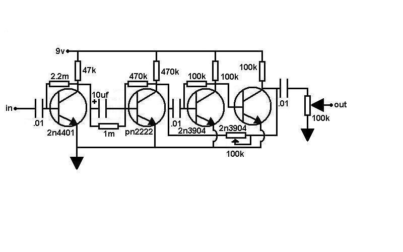
This purports to be a schematic for the RNG:

Image

I've not correlated this schematic with the layout you posted, but it's a fine reference for analysis.

So, 2nd cap is a polarized electrolytic (+10uf) oriented to block the DC supplied to the collector of the preceding transistor while passing AC signal. The gating you describe is probably more of a function of bias point of the transistor - which was previously fed more DC from the preceding stage.

I like to do voltage dividers for bias, I notice that this schematic does not ground reference the signal path (probably part of its charm), so if you're hoping to change the characteristics without impacting the nature too much I'd start with playing with resistor values instead of cap values, because a cap should block DC no matter what its size.
User avatar
moid
experienced
experienced
Posts: 715
Joined: Sun May 03, 2015 6:35 pm
Contact:

Re: Weird question about Starve knobs

Post by moid »

Whoops I forgot to check this post (it's been a bad week), Thanks for your comments again. I really have a lot to learn about electronics, thanks for stopping me before I went in the wrong direction entirely! I find it hard to understand how the capacitor after the transistor blocks the current going to its collector - but that's probably my general ignorance of all thing electronic. Should I think of electrolytic capacitors as something to block / reduce voltage and the resistors would lower the volume of the audio? Do other capacitor types have an effect on frequency passing then? And if I want to gate a signal, having a high value resistor that the audio path has to travel through would only allow the loudest signals through? If that's true then maybe I could make a variable gate effect by using a potentiometer perhaps? 100K or higher - and if this works would the audio go into lug 3, the audio out be on lug 2 and then what would lug 1 do? Be attached to ground? Or attached to another resistor that then goes to ground? Thanks for your thoughts, but please get your pedals built first; my work is going to be horrid for the rest of this month and there's no way I'll be able to touch a soldering iron until early November now :(
User avatar
crochambeau
IAMILF
IAMILF
Posts: 2204
Joined: Mon Jul 20, 2015 12:49 pm
Location: Cascadia
Contact:

Re: Weird question about Starve knobs

Post by crochambeau »

Oh man, there's a huge rabbit hole here... forgive me for the long post, you've caught me mid-beer.

moid wrote:I find it hard to understand how the capacitor after the transistor blocks the current going to its collector


Capacitors block DC but pass AC, current is just the movement of electrons, and therefore exists in both AC and DC domains. For all intents and purposes, the DC elements we concern ourselves with (in this sort of thing - low level AC signal handling) are mainly just establishing potentials - which affect operational ranges of the actives - be they discrete transistors or IC opamps.

So, in short, the cap will pass the AC signal while blocking the DC potentials from one stage to the next.

moid wrote:Should I think of electrolytic capacitors as something to block / reduce voltage and the resistors would lower the volume of the audio?


In short: caps block DC and pass AC while resistors restrict or load down both class of signal.

Electrolytics are a somewhat special class of capacitor, in that they are an electro-chemical part as opposed to a strict physical geometry part; this results in a polar dissimilarity, so if you place it in circuit such that the DC potential of the negative side bears a positive voltage in relation to the positive leg of the part IT LEAKS LIKE A MOTHERFUCKER. How MUCH it leaks is going to largely hinge on the chemical composition of the electrolyte, and if you're ever in a pinch, placing two electrolytics + to + and treating them as a single part will create a non polarized capacitor.

You may not (as in: probably won't) run into them, but Tantalum caps are known to explode when installed polarity reversed, this is further exacerbated by the manufacturer's habit of putting the STRIPE on the POSITIVE lead. So if you wind up with little balloon looking things - pay attention.

moid wrote:Do other capacitor types have an effect on frequency passing then?


If you want to swim in polluted waters, you can research the opinions of people as to what different types of caps do to sound. TAKE IT ALL WITH A GRAIN OF SALT, and honestly, since you indicate you're just jumping in I would advise you to not concern yourself with that just yet...

What you SHOULD concern yourself with is value of the capacitor. A 100 pf cap will pass far more limited frequencies than a 10 uf cap (100,000 times larger value). Think of a cap as a short circuit for AC signal, which will ALWAYS favor higher frequencies and reach a point in which it will begin to act like a resistance to lower frequencies. So, the bigger the better, within reason - so far as AC is concerned. There's a complication regarding DC I'm going to gloss over since this is turning into a tome here. Suffice to say: slap any cap in there, if you lose bass response (and the cap is in SERIES with your signal path) raise the value, if you lose treble (and the cap is BLEEDING signal to ground) decrease your value.

No cap is perfect, and some people will get rabid about them, again, don't take anyone's opinion but your own too seriously.

moid wrote:And if I want to gate a signal, having a high value resistor that the audio path has to travel through would only allow the loudest signals through?


No. The resistor is a constant that will affect loud and soft levels more or less equally. What the resistor DOES do (one of its MANY functions) is set the bias level of a transistor. Imagine for a moment that you are the source signal, and the AC variation is essentially you jumping up and down on a trampoline.. now, the next stage is fed from line of sight, and it is a pie plate nailed to a tree. So long as you can see the pieplate, it will collect and deliver your signal to the next stage.

However, the next stage is some curmudgeonly old fuckwit who hates people looking at his pie plate, so he's built a fence between you, having fun on your trampoline, and his precious pie plate that is covered in ants and old cherry pie. RESISTORS define how tall that fence is, how tall the trampoline is, how springy the trampoline surface is, and the height of a branch that happens to be over your head is. Ideally, in the sense of hifi, the fence is low and the overhanging branch is high, and everything else is just right that you always have the pieplate in sight.

The gating/sputtering I think you're talking about is what happens when the fence is raised to the point at which you only see the pieplate part of the time, the remaining time NOTHING is conducted from point A to point B as you're stuck behind the wall. That is a function of DC bias, which *usually* hinges on resistance. Always a good idea to directly read voltage as a starting point though.

moid wrote:If that's true then maybe I could make a variable gate effect by using a potentiometer perhaps?


While the premise on which you extend this inquiry is incorrect, you can indeed affect bias with a pot. I would determine the lowest and highest useful voltage bias points on the base of the transistor, then plot that as a *ratio*, stick your 100K or whatever in a voltage divider so that the travel goes from one end of your useful range to the other.
User avatar
moid
experienced
experienced
Posts: 715
Joined: Sun May 03, 2015 6:35 pm
Contact:

Re: Weird question about Starve knobs

Post by moid »

Sorry about the slow reply - I really appreciate it, this month is crazy at work and I know I won't be able to do anything outside of sleep and work until I finish a deadline for the end of this month :( This makes me want to try more new things... if I just had some time. Hmm do I take the red pill or the blue pill? Thank you for writing such a lot; I really am somewhat out of my depth here! I feel I understand the capacitors and resistors better now, I definitely didn't realise about there being two different currents in the pedal; I assumed they were DC only - is DC the power and AC the audio signal? Thanks for the warning about tantalums; I've not used those so far but I will remember it! OK I will have to play with capacitors; I think I could try splitting my audio signal into different frequency bands with them if I understood you correctly, and then add an effect to each stream of audio and then maybe re combine them back together again... that could be fun.

I have a lot to think about and learn more about; thank you very much!
Post Reply