It was not my intention to cause any problems, i'm new to this whole forum thing so not exactly clear on the rules. I'm just trying to build up my knowledge, i'm basically new to this whole pedal building thing. Thank you for all of your responses, they've been extremely interesting and really helpful. For me the price tag is an issue but i'd also like to try and teach myself how to build pedals, i'm beginning to realise what a long and daunting process this is going to be. So to clarify on what some of you have been saying, if i were to hypothetically build this type of pedal the best way might be to use the 555 thing and an optocoupler? I think i'm beginning to get my head round this...the 555 is used to make an LED flash at a rate controllable with a pot? This is used in conjunction with the optocouper which drops the feedback signal in and out? Schematics scare the crap out of me so i think OHNOHO is safe for a while.
Thanks again
Utter Stutter Feedback Looper
Moderator: Ghost Hip
Forum rules
The DIY forum is for personal projects (things that are not for sale, not in production), info sharing, peer to peer assistance. No backdoor spamming (DIY posts that are actually advertisements for your business). No clones of in-production pedals. If you have concerns or questions, feel free to PM admin. Thanks so much!
The DIY forum is for personal projects (things that are not for sale, not in production), info sharing, peer to peer assistance. No backdoor spamming (DIY posts that are actually advertisements for your business). No clones of in-production pedals. If you have concerns or questions, feel free to PM admin. Thanks so much!
-
paddy398

- involved

- Posts: 51
- Joined: Fri Feb 22, 2013 1:50 pm
- Location: North London
-
Dr Satan

- committed

- Posts: 196
- Joined: Thu Aug 25, 2011 4:11 pm
- Location: North of the ATL.
Re: Utter Stutter Feedback Looper
Yes, you can google 555 tremolo schematic and find an appropriate diagram. It may not show an opto isolator, but the function is the same. A light source is used to vary resistance, be it to ground or in the signal path. As with most circuits, there is more than one way to accomplish the same goal.
-
chutneyfarmer

- experienced

- Posts: 892
- Joined: Mon Jan 05, 2009 3:48 pm
- Location: Ireland
Re: Utter Stutter Feedback Looper
paddy398 wrote:It was not my intention to cause any problems, i'm new to this whole forum thing so not exactly clear on the rules. I'm just trying to build up my knowledge, i'm basically new to this whole pedal building thing. Thank you for all of your responses, they've been extremely interesting and really helpful. For me the price tag is an issue but i'd also like to try and teach myself how to build pedals, i'm beginning to realise what a long and daunting process this is going to be. So to clarify on what some of you have been saying, if i were to hypothetically build this type of pedal the best way might be to use the 555 thing and an optocoupler? I think i'm beginning to get my head round this...the 555 is used to make an LED flash at a rate controllable with a pot? This is used in conjunction with the optocouper which drops the feedback signal in and out? Schematics scare the crap out of me so i think OHNOHO is safe for a while.
Thanks again
Don't worry about it man. Nothing bad actually happened in this thread so I don't know why it is being implied.
Nobody asked for schematics/layouts, nobody posted schematics/layouts.
If we're now not supposed to be talking about components or approaches for certain types of pedals we may as well shut this subforum now.
Talk about a completely unneccessary argument, jeez.
Good Transactions With:
Achtane
in2thegapagain85
Proroby
zezozeceglutz
MEC
echobaseone
Skullservant
Rob Fossil
Psyre
Achtane
in2thegapagain85
Proroby
zezozeceglutz
MEC
echobaseone
Skullservant
Rob Fossil
Psyre
-
paddy398
- involved
- Posts: 51
- Joined: Fri Feb 22, 2013 1:50 pm
- Location: North London
Re: Utter Stutter Feedback Looper
I've basically got my head round this now i think, just need a couple of things clarifying. Probably silly questions but, with this:
http://mikmo.dk/veroboard%20555%20lfo.GIF
Which way round is the LED wired? Which side would be positive and which would be negative.
Also, hooking this up to a feedback looper circuit like this one:
http://farm4.static.flickr.com/3592/377 ... 0ca8_o.jpg
Does the - coming out of the 555 circuit hook up to the + on the DC jack of the feedback circuit? And the + coming off the 555 circuit hook up to the - on the DC jack?
Thanks a lot
-
eatyourguitar

- IAMILFFAMOUS

- Posts: 3127
- Joined: Sun Oct 03, 2010 12:37 pm
- Location: USA, RI
Re: Utter Stutter Feedback Looper
chutneyfarmer wrote:If we're now not supposed to be talking about components or approaches for certain types of pedals we may as well shut this subforum now.
Talk about a completely unneccessary argument, jeez.
its all about context. if the title of this thread did not include the name of a builder on ILF or if Lawrence (Ohno) wants to come and share his work, I would have already posted a schematic by now.
ask me how to build a feedback looper with a 555 and a vactrol, done, schematic posted. Paddy PM'ed me and I gave him all the info he needed. see how easy it was to not piss off the people that own the forum? these are the rules that were handed down to everyone from Tom. I'm just a nice guy who wants to keep everyone happy and respect everyone equally the best way I can figure that out. please, please, don't leave. I know I will miss you all dearly. I really mean that too. on a side note, have you ever tried emailing a pedal company or a synth company and asking them for schematics or permission to post guts? I have and it works. lots of these builders are super nice guys that will give you the world if you just ask for it. not a single person PM'ed Lawrence as far as I know. the very first pedal I built was from me emailing a builder about a $175 pedal and he gave me a schematic! true story. thats what being nice gets you.
the ethics debate of DIY is old, real old. I agree with everyone that reverse engineering is the main source of learning. I agree that no one has the right to keep secrets especially when the technology is pretty simple recycled old shit. so we all agree then right?
P.S. since the discussion is already going, this might be a good time to learn about 555's and vactrols. keep it going guys. make it educational.
WWW.EATYOURGUITAR.COM <---- MY DIY STUFF
-
Dr Satan
- committed
- Posts: 196
- Joined: Thu Aug 25, 2011 4:11 pm
- Location: North of the ATL.
Re: Utter Stutter Feedback Looper
paddy398 wrote:I've basically got my head round this now i think, just need a couple of things clarifying. Probably silly questions but, with this:
http://mikmo.dk/veroboard%20555%20lfo.GIF
Which way round is the LED wired? Which side would be positive and which would be negative.
Also, hooking this up to a feedback looper circuit like this one:
http://farm4.static.flickr.com/3592/377 ... 0ca8_o.jpg
Does the - coming out of the 555 circuit hook up to the + on the DC jack of the feedback circuit? And the + coming off the 555 circuit hook up to the - on the DC jack?
Thanks a lot
http://arlontronique.files.wordpress.co ... 6/led1.gif
As for the second part of your question, I'm not sure I follow you. + is +, - is - You still need a photoresistor wired into the send or return of the feedback loop so that the flashing LED will do what it's supposed to do. You're "optically isolating" the audio from the power which is why the use of an opto isolator/opto coupler is a good choice for this circuit, since it is basically an LDR in a smaller package that you don't have to build.
-
paddy398
- involved
- Posts: 51
- Joined: Fri Feb 22, 2013 1:50 pm
- Location: North London
Re: Utter Stutter Feedback Looper
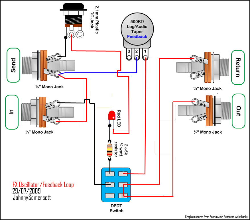
Here's what i've come up with, simple diagram i know but schematics terrify me. This is just my interpretation of the circuit, have had a lot of help from some lovely people which i really appreciate
http://s22.postimage.org/i38f4psyp/Feed ... _build.jpg
http://s22.postimage.org/i38f4psyp/Feed ... _build.jpg
-
Dr Satan
- committed
- Posts: 196
- Joined: Thu Aug 25, 2011 4:11 pm
- Location: North of the ATL.
Re: Utter Stutter Feedback Looper
I don't see why that shouldn't work.
-
paddy398
- involved
- Posts: 51
- Joined: Fri Feb 22, 2013 1:50 pm
- Location: North London
Re: Utter Stutter Feedback Looper
Great stuff, cheers. If i wanted to keep the 500k feedback pot as well as the photoresistor would it just be a case of wiring it like this?
http://s12.postimage.org/3xm4j15i5/Feed ... ck_pot.jpg
thanks a lot
http://s12.postimage.org/3xm4j15i5/Feed ... ck_pot.jpg
thanks a lot
-
Bellyheart

- IAMILFFAMOUS
- Posts: 5791
- Joined: Mon Nov 10, 2008 11:23 pm
- Location: Richmond, Va
Re: Utter Stutter Feedback Looper
Post dat when it's operating.
-
Dr Satan
- committed
- Posts: 196
- Joined: Thu Aug 25, 2011 4:11 pm
- Location: North of the ATL.
Re: Utter Stutter Feedback Looper
paddy398 wrote:Great stuff, cheers. If i wanted to keep the 500k feedback pot as well as the photoresistor would it just be a case of wiring it like this?
http://s12.postimage.org/3xm4j15i5/Feed ... ck_pot.jpg
thanks a lot
It kinda depends on how you want it to work. With the pot in one extreme, you'll have no stutter effect at all, but in the other you'll have a lesser stutter effect than not having the pot in there. By putting the resistance in parallel, you lower it. So, say the photoresistor is 500K full dark, that means you'll only have 250K with a 500K in parallel. The photoresistor would have to be 10M full dark to even come close to being 500K with a 500K in parallel. I'm not saying it won't work, but I don't think it's going to work how you want it to. Now, if you put the pot in series, it might be more what you're after. But I don't know. You need to put it on a bread board and play with it.
-
paddy398
- involved
- Posts: 51
- Joined: Fri Feb 22, 2013 1:50 pm
- Location: North London
Re: Utter Stutter Feedback Looper
Any chance you'd be able to edit my diagram so that the feedback pot was wired in series? I'd like to have control over the amount of feedback using the pot so i don't kill people when playing live. Thanks a lot
-
Dr Satan
- committed
- Posts: 196
- Joined: Thu Aug 25, 2011 4:11 pm
- Location: North of the ATL.
Re: Utter Stutter Feedback Looper
To put it in series just remove the orange/red going from the top right lug of the DPDT switch going to the photoresistor, and move the green that goes from lug 2 of the pot from the send jack to the leg of the photoresistor that you just disconnected from the switch. So that it goes from the switch---------to the outer lug of the pot---then from the center lug of the pot---------to the right leg of the photoresitor.
-
paddy398
- involved
- Posts: 51
- Joined: Fri Feb 22, 2013 1:50 pm
- Location: North London
Re: Utter Stutter Feedback Looper
Thanks a lot man! So this looks like the final draft...
http://s14.postimage.org/56qd22yi9/Feed ... pot_wi.jpg
As soon as my next student loan comes in i'm going to build this little git!
Thanks again for all your help
Patrick
http://s14.postimage.org/56qd22yi9/Feed ... pot_wi.jpg
As soon as my next student loan comes in i'm going to build this little git!
Thanks again for all your help
Patrick