Page 2 of 3
Re: DIY Synths
Posted: Thu Aug 23, 2012 4:36 pm
by skullservant
500k from what I can remember!
Re: DIY Synths
Posted: Fri Aug 24, 2012 1:00 pm
by multi_s
aen wrote:YYYEESSSS!
we should make an ilf modular.

Re: DIY Synths
Posted: Fri Aug 24, 2012 1:04 pm
by skullservant
IM IN
Re: DIY Synths
Posted: Fri Aug 31, 2012 4:46 pm
by Moustache_Bash
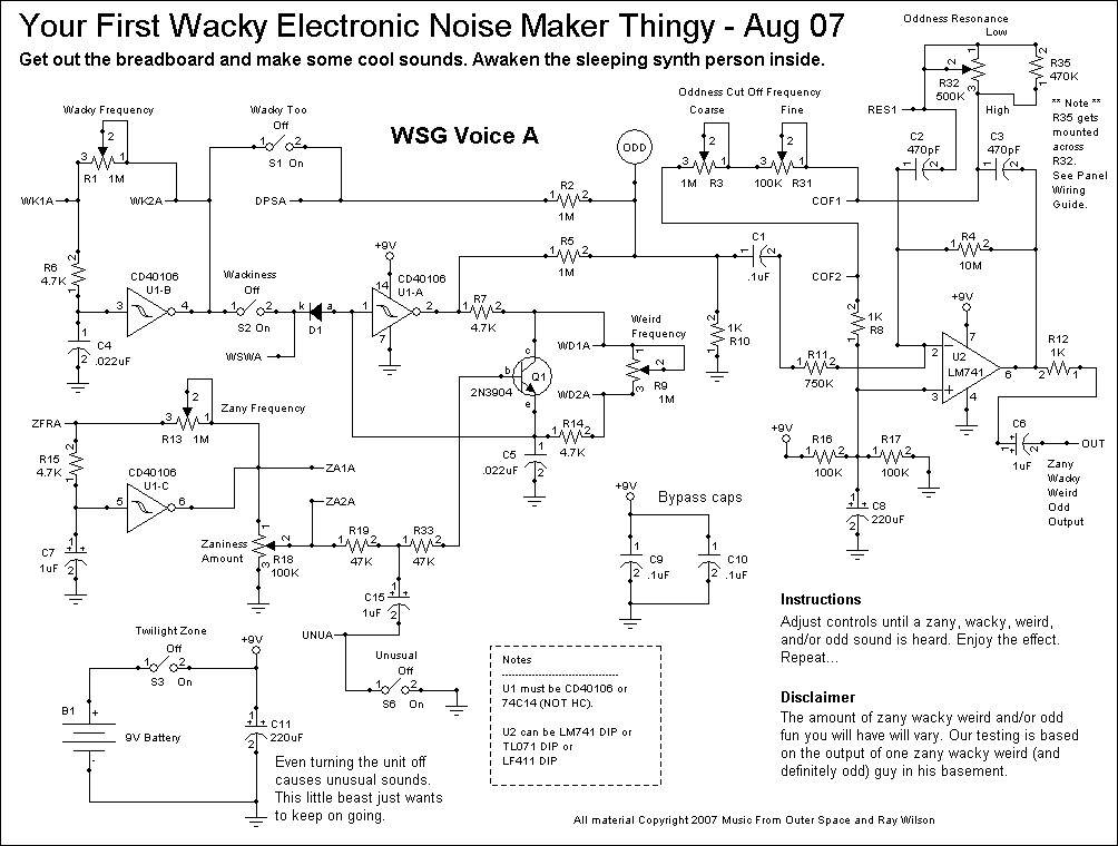
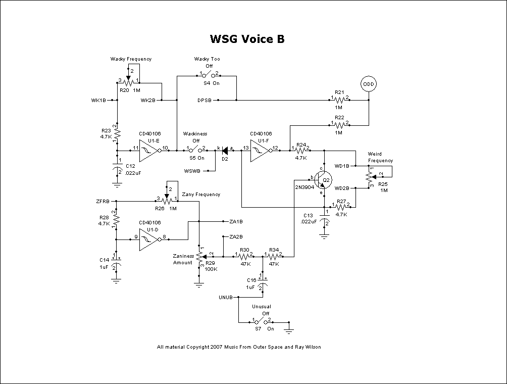
The parts of the schematic that are circled and say "ODD," are those just continuations of the circuit like the various DPSB/WPSB/UNUB/etc are?


Re: DIY Synths
Posted: Fri Aug 31, 2012 6:39 pm
by multi_s
i *think* it is just there to tell you they are connected to each other on the circuit/pcb even though they are on different pages of the schematic. They are both the outputs of the respective oscillators shown on each schematic page and that point is just before the resonant filter which feeds the actual output jack so it makes sense.
Re: DIY Synths
Posted: Fri Aug 31, 2012 6:53 pm
by Moustache_Bash
multi_s, coming through for me again! Thanks. I think you're right, though. I'll find out as soon as I'm done breadboarding this.
Re: DIY Synths
Posted: Fri Aug 31, 2012 10:09 pm
by multi_s
good luck, its a pretty fun circuit.
Re: DIY Synths
Posted: Sat Sep 01, 2012 2:51 pm
by BrentMpls
Do you have some samples of yours MB?
Re: DIY Synths
Posted: Sat Sep 01, 2012 7:12 pm
by soldersqueeze
That WSG is a nice synth, and is stupidly fun to play with. The PCB is available and is good quality- i used two of them to build this stereo version-

A lot of wire though, and if you're as lazy as me it ends up looking like this inside

I reversed the layout of the controls and sweep of the pots down the centre for a nice mirror image layout. I mirrored all the control labels too (they all say the same thing anyway- "turn me", and "switch me" for the switches).
Highly recommended project

Re: DIY Synths
Posted: Sat Sep 01, 2012 10:07 pm
by multi_s
looks awesome!
Re: DIY Synths
Posted: Fri Sep 07, 2012 3:09 pm
by BrentMpls
skullservant wrote:You can put LEDs for the rate of the LFOS too, and those blink!
I also added a master volume knob, power starve knob, and a SHO booster at the end for when it is starved and the signal gets too low. One of my favorite synths and I want to build another since I sold this one!

Super cool!
Re: DIY Synths
Posted: Fri Sep 07, 2012 4:45 pm
by Moustache_Bash
BrentMpls wrote:Do you have some samples of yours MB?
Sorry, I haven't finished it yet. As usual, I'm like between 4 different projects right now. Haha, I can never just sit down long enough to finish one through and through. In due time, though, sir.
Re: DIY Synths
Posted: Mon Sep 10, 2012 6:07 pm
by soldersqueeze
Here is a rubbish demo of a WSG which probably doesn't do it justice but gives an idea of the kind of things it can do. Straight into the desk with no compression or reverb- it's as dry as it gets. I turned the input gain down at around 1:19 because it was clipping. Hope it is of some use.
[soundcloud]http://soundcloud.com/gary-sronghorn/crapwsgdemo[/soundcloud]
Re: DIY Synths
Posted: Mon Sep 10, 2012 6:19 pm
by soldersqueeze
Oh, and as far as other MFOS stuff goes, check out the new Noise Toaster and Alien Screamer models. I am waiting for delivery of a couple of Noise Toaster boards, and as soon as I have one working I'll post pics and a demo. I love MFOS- Ray is a god damn genius!
Re: DIY Synths
Posted: Tue Sep 25, 2012 1:43 pm
by Moustache_Bash
Moustache_Bash wrote:The parts of the schematic that are circled and say "ODD," are those just continuations of the circuit like the various DPSB/WPSB/UNUB/etc are?


So, still knockin this out at turtle lightning speeds (part of the reason is I didn't buy the kit/PCB, so I've just had it sitting in the breadboard lil bits at a time, but I am also not too smart sooooo) and I was wondering about the jumpers again. In instances where it says "WK1A" would you guys agree it would connect to "WK1B" rather than "WK2A?" My reasoning for that is I would think they would just connect the lines as WK1A and WK2A are on the same page. Then, it seems to change the jumpering lettering a bit, because on page 1 of the schematic you got "COF1" and "COF2." I would assume those are connected as there is no COF# business going on page 2. And finally, RES1. Where the hell does that go? I'm gonna have to look on MFOS' website and see if those connections have some kind of offboard wiring going on or something, or if they don't mind emails from simpletons.
Anyways, if you guys have any ideas I would greatly appreciate it

P.S. Apologies for the terrible use of commas.


