Page 9 of 10
Re: Snowflake kit thread!
Posted: Thu Feb 03, 2011 7:10 pm
by TweedBassman
kinski wrote:Quick question...Is there a way to bypass the texture pot, instead of the gain. I find that my two favorite settings are:
1. Gain, all the way up, and Texture all the way down.
2. Gain, all the way up, and Texture all the way up.
So, it would be nice to have the Texture pot on a switch, instead of the gain pot. Even cooler, would be to have a mini-toggle switch that would set the 2nd footswitch to bypass either the Gain or the Texture pot. Anyone know how to do any of this?
the footswitch wiring for bypassing the texture control (what you want to do) is exactly the same as the gain bypass. So, you can add a DPDT toggle to have the footswitch working either the standard gain control (2 spots on the board) or have the footswitch bypass the texture pot; you'd just need to add two additional wires to the texture pot and send those to the DPDT.
comtrails70 wrote:How does the starve pot sound??
not too crazy but i think it can clean up some higher gain settings.
worth at least trying out (maybe directly at the power source so you dont have to cut the trace)
Actually, i found the starve to add a lot of grit and fuzz to the sound; it lowers the volume just a hair, but there's still a ton of volume left. use a 2k pot, it will shut off after about 3/4ths of the way but there's some cool sounds in there.
futuresailors wrote:Anyone try throwing one of these in a feedback loop?
It basically just shuts off. no cool oscillation or anything.
Re: Snowflake kit thread!
Posted: Fri Feb 04, 2011 7:46 am
by chutneyfarmer
Finished off my build this morning. Very impressed! A nice range of sounds and it stacks lovely with my Red Llama clone
")
tis shoegaze heaven. I think it may replace the Supercollider on my board to be honest. When using the Supercollider, it tends to send me towards a more doomy depressing sound and way of playing. The Fingerprint/Snowflake seems to inspire more melodic playing which is what I want to do more of. It may be just a tad too trebly but nothing I can't live with
very happy!
Re: Snowflake kit thread!
Posted: Fri Feb 04, 2011 11:01 pm
by futuresailors
TweedBassman wrote:
It basically just shuts off. no cool oscillation or anything.
This gives me a sad...

Re: Snowflake kit thread!
Posted: Tue Mar 01, 2011 2:38 am
by digitalzombie
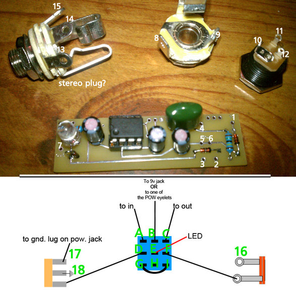
Hey guys and gals. Just getting into building my kit and I have a couple newbie questions. I've only built a diy mod kit before, so some of my questions might seem really junior level as I'm not going to even try to sound like I know what I'm talking about, but I have asked questions online before so I'll try to be as concise as possible and reference the picture I'm attaching. As you can see I've labeled everything I possibly have questions about on the pictures. I'm trying to build the single footswitch version to spec, btw:
Question 1: Where do I wire the ground from PCB eyelet 2 to?
Question 2: I understand the red wire of the LED goes to pole E on the footswitch, but where does the black wire go?
Question 3: In the diagram, what are the two objects represented on either side of the footswitch diagram (16-18)?
Question 4: The diagram states "to gnd. lug on pow. jack". Once I get Question 3 answered, is this going to 10 or 12? (I imagine it's one of these since the included instructions make it look like 11 is to be wired to PCB 1.)
Question 5: Did I receive a stereo jack by mistake? If so, that's fine I can just buy a mono jack from Radio Shack, but curious if I can or even should use the one provided.
Question 6: Can I just solder a small piece of wire to jump poles I and G on the footswitch? (That's what it's telling me to do, right?)
Um... I think that's all the questions I have for now, but I'm sure I'll have follow ups. Any help would be appreciated. Thanks folks.
Re: Snowflake kit thread!
Posted: Wed Mar 02, 2011 12:18 am
by kinski
[quote="TweedBassman"][quote="kinski"]
the footswitch wiring for bypassing the texture control (what you want to do) is exactly the same as the gain bypass. So, you can add a DPDT toggle to have the footswitch working either the standard gain control (2 spots on the board) or have the footswitch bypass the texture pot; you'd just need to add two additional wires to the texture pot and send those to the DPDT.
[quote="comtrails70"]
Hey, sorry for my delay. I never got a notice that there was a reply and I just saw this! Thanks! Okay, I'd like to do this. Remove the gain bypass and add the texture bypass. Amateur question here....how exactly do I wire the DPDT to to Texture pot? I'm using a mini 2-lug momentary switch.
Thanks a lot!
Re: Snowflake kit thread!
Posted: Thu Mar 03, 2011 12:19 am
by FuzzHugger
digitalzombie wrote:Hey guys and gals. Just getting into building my kit and I have a couple newbie questions. I've only built a diy mod kit before, so some of my questions might seem really junior level as I'm not going to even try to sound like I know what I'm talking about, but I have asked questions online before so I'll try to be as concise as possible and reference the picture I'm attaching. As you can see I've labeled everything I possibly have questions about on the pictures.
I'm trying to build the single footswitch version to spec, btw:--Question 1: Where do I wire the ground from PCB eyelet 2 to?
--Question 2: I understand the red wire of the LED goes to pole E on the footswitch, but where does the black wire go?
--Question 3: In the diagram, what are the two objects represented on either side of the footswitch diagram (16-18)?
--Question 4: The diagram states "to gnd. lug on pow. jack". Once I get Question 3 answered, is this going to 10 or 12? (I imagine it's one of these since the included instructions make it look like 11 is to be wired to PCB 1.)
--Question 5: Did I receive a stereo jack by mistake? If so, that's fine I can just buy a mono jack from Radio Shack, but curious if I can or even should use the one provided.
--Question 6: Can I just solder a small piece of wire to jump poles I and G on the footswitch? (That's what it's telling me to do, right?)
Um... I think that's all the questions I have for now, but I'm sure I'll have follow ups. Any help would be appreciated. Thanks folks.
I don't know where to begin, but I'll try!
Hopefully I get all this correct, cause the number system is confusing me. Also, sorry if I get repetitive with some answers--some of these things are connected (literally!).
--Question 1: The PCB gets grounded to the rest of your ground points. All your ground points get connected together. So PCB ground, LED ground, input jack lug 14/18, (and your power jack ground, if you're not going to use a battery clip) all get connected.
--Question 2: The LED's black wire is ground. That goes to ground. (A good point to run the LED's ground is to the middle lug of the stereo jack, what you have numbered as 14/18.)
--Question 3: Those objects are the jacks...stereo on the left, mono on the right. (Your numbering...14/18 are the same thing, 15/17 are the same thing, and 9/16 are the same thing.)
--Question 4: Ground lug of the power jack is what you have numbered as 10. You only have to connect this to 17 on the stereo jack if you're going to add a battery clip. Otherwise, connect the ground lug of the power jack (10) to ground.
--Question 5: It's a stereo jack, normally used for switching your battery on/off. If you're not adding a battery clip, just ignore that extra lug on the stereo jack (what you have numbered as 17). And run the power jack's ground lug to ground.
--Question 6: That's exactly right.
You have the ground lug of the stereo plug numbered as 14 in the pic and 18 in the diagram...but that lug is your ground point. Number 17/15 gets connected to number 10--ground lug of the power jack. If you're not adding battery operation, forget that lug on the jack...and connect the power jack's ground (#10) to ground with everything else.
Other things......A goes to 4......C goes to 7......B goes to 11......11 also gets connected to 1. On the PCB, 3 and 2 are both grounds...pick one, or use the other to run your LED ground to, if it's more convenient than running your LED ground to 14/18 (ground on the input jack). 9/16 is a ground lug on your output jack. It's left blank.
Re: Snowflake kit thread!
Posted: Thu Mar 03, 2011 1:46 pm
by digitalzombie
Wow, sweet detail Tom. Thanks a bunch. I'll definitely be updating how well this works, but I think all of my questions have been answered.
Now just to drill this stupid enclosure and I'll be set...
Re: Snowflake kit thread!
Posted: Wed Apr 13, 2011 2:50 am
by Eric!
needs more pics
Re: Snowflake kit thread!
Posted: Wed Apr 27, 2011 1:35 pm
by ARC Effects
What taper pots are supposed to be used with this?
Re: Snowflake kit thread!
Posted: Sat Apr 30, 2011 12:40 pm
by ARC Effects
Bueller?
I'm going to assume 10k Audio, 1K Linear, 500k Reverse Audio?
Re: Snowflake kit thread!
Posted: Thu Jul 07, 2011 1:54 pm
by mdclark58
Does the size of the LED on the board matter? I'd like to sub out a brighter, bigger LED and run it to a plexi baseplate so that it will light up when I rock the pedal hard.
Also, does the 9v tap matter? I bought the complete kit, but the jack was forgotten. I bought it back in December and have only now had time to build. The only jack that I could find around me was a correctly sized panel mount jack. It has a metal housing, unlike the plastic jack that you see on virtually every pedal.
Re: Snowflake kit thread!
Posted: Sat Jul 09, 2011 12:44 pm
by Gone Fission
Are the kits going to be restocked?
Re: Snowflake kit thread!
Posted: Tue Jul 12, 2011 7:31 pm
by nieh
Gone Fission wrote:Are the kits going to be restocked?
Re: Snowflake kit thread!
Posted: Mon Jul 18, 2011 11:15 pm
by mdclark58
Bump for unanswered questions...
Re: Snowflake kit thread!
Posted: Tue Jul 19, 2011 6:48 am
by AC128
Gone Fission wrote:Are the kits going to be restocked?
pleeease?