a really really big fuzz
Moderator: Ghost Hip
Forum rules
The DIY forum is for personal projects (things that are not for sale, not in production), info sharing, peer to peer assistance. No backdoor spamming (DIY posts that are actually advertisements for your business). No clones of in-production pedals. If you have concerns or questions, feel free to PM admin. Thanks so much!
The DIY forum is for personal projects (things that are not for sale, not in production), info sharing, peer to peer assistance. No backdoor spamming (DIY posts that are actually advertisements for your business). No clones of in-production pedals. If you have concerns or questions, feel free to PM admin. Thanks so much!
Re: a really really big fuzz
![]() by eatyourguitar » Sat Feb 27, 2016 12:59 am
by eatyourguitar » Sat Feb 27, 2016 12:59 am
Did i screw it up? Im not sure. I have some actual transistors that are completely non-standard. The eagle part is probably madbean that probably came from gusmarkov. You can make the pcb fit your transistor of choice or you can find a part that fits the pcb. I can totally change it if the other way is more popular.
WWW.EATYOURGUITAR.COM <---- MY DIY STUFF
-
eatyourguitar

- IAMILFFAMOUS

- Posts: 3127
- Joined: Sun Oct 03, 2010 12:37 pm
- Location: USA, RI
Re: a really really big fuzz
![]() by Ben79 » Mon Mar 07, 2016 8:59 am
by Ben79 » Mon Mar 07, 2016 8:59 am
I got this thing together. Some amazing sounds and weirdness in there. I'll post up a montage of video clips when I get some time.
Perhaps I've done something wrong but….
I think the tone is wired backwards (unless you call it a treble cut)
The Dirt/Mud pot doesn't seem to do anything
The switches do nothing….? That's odd….
I'm struggling to get anything but extreme fuzz from it, that could be because the gain is stuck on max.
Perhaps I've done something wrong but….
I think the tone is wired backwards (unless you call it a treble cut)
The Dirt/Mud pot doesn't seem to do anything
The switches do nothing….? That's odd….
I'm struggling to get anything but extreme fuzz from it, that could be because the gain is stuck on max.
-
Ben79

- experienced

- Posts: 510
- Joined: Thu Nov 01, 2012 6:16 pm
- Location: Germany
Re: a really really big fuzz
![]() by eatyourguitar » Mon Mar 07, 2016 11:08 am
by eatyourguitar » Mon Mar 07, 2016 11:08 am
My intention was that tone knob is brighter when fully CW. The switch should do something. Can you check continuity from the pcb switch pads throught the switch with the switch closed? I can fix errors in the pcb but i want to be %100 sure there is a problem on the PCB. I am away from a computer right now i will look at the schematic later.
WWW.EATYOURGUITAR.COM <---- MY DIY STUFF
-
eatyourguitar
- IAMILFFAMOUS
- Posts: 3127
- Joined: Sun Oct 03, 2010 12:37 pm
- Location: USA, RI
Re: a really really big fuzz
![]() by Ben79 » Wed Mar 09, 2016 8:16 am
by Ben79 » Wed Mar 09, 2016 8:16 am
'THE' switch? It's just one switch? So it's a dpdt not two spdt?
I presumed from the layout of the PCB and the labelling SW1 and SW2 that it was 2 switches. Still, 2 spdt amount to the same thing...
I've checked continuities and they're all good.
It's always possible I've overlooked something so let's see what Curt and Multi get.
I presumed from the layout of the PCB and the labelling SW1 and SW2 that it was 2 switches. Still, 2 spdt amount to the same thing...
I've checked continuities and they're all good.
It's always possible I've overlooked something so let's see what Curt and Multi get.
-
Ben79
- experienced
- Posts: 510
- Joined: Thu Nov 01, 2012 6:16 pm
- Location: Germany
Re: a really really big fuzz
![]() by crochambeau » Wed Mar 09, 2016 11:34 am
by crochambeau » Wed Mar 09, 2016 11:34 am
I'll spend a little time with it today, it's built - just not assembled into the enclosure yet.
I too am operating under the impression that it is two discrete SPDT switches (it seems the orientation of pads - assuming board mount controls - confirms this), switching in mine is also not pronounced, though I recall some change when the controls were in a certain range. It's all very cryptic, I know, I've been holding off posting (or PM if you prefer) until I can get my observations sorted.
I also corroborate DIRT/MUD control as being non-responsive, I have been meaning to pull the pot and test it to confirm function.
I think you and I are the Alpha team, pretty sure multi has a full plate to the degree that makes taking this on a practical impossibility.
I've got to get off my ass and bring to reality that what has been quoted through existence.
Rochambeau Musical Apparatus
Reverb storefront
Shark Tank
Rochambeau Musical Apparatus
Reverb storefront
Shark Tank
-
crochambeau

- IAMILF

- Posts: 2162
- Joined: Mon Jul 20, 2015 12:49 pm
- Location: Cascadia
Re: a really really big fuzz
![]() by multi_s » Thu Mar 10, 2016 2:29 pm
by multi_s » Thu Mar 10, 2016 2:29 pm
i thought it got mentioned earlier but i don't remember what the rational was, and I don't see it in the thread but haven;t looked that closely, the pcb seems a bit different from the orignal schem, but sw1_a in the original schem does nothing because both toggles are on the same net. sw1_b adds some clipping diodes, so if the signal is not large enough it will not change anything..
My interpretation of the pcb and what the switches do:
looks like sw1 on pcb is sw1_b on teh op schematic?
sw2 might be sw1_a with pin 3 disconnected, it looks disconnected on the cad shot of pcb.
if this is the case it looks like sw2 adds the dirt/mud control to the circuit. if this is not switched the right way, the dirt/mud control will do nothing, since it is not in the signal path/in the circuit. Then you use sw1 to pick whether or not you want clipping diodes in the path.
that's just my guess of the op's intent, i am not making one, but if you look at the schem you can probably see what im saying, it also corroborates in some ways with your build experience.
s
-
multi_s

- IAMILF
- Posts: 2090
- Joined: Mon Feb 15, 2010 9:00 pm
Re: a really really big fuzz
![]() by eatyourguitar » Sun Mar 13, 2016 11:28 am
by eatyourguitar » Sun Mar 13, 2016 11:28 am
major mistake found!
dirt/mud switch must not be connected to the Q3 emitter. instead it must be connected to Q3 collector. half the fuzz factory (and also PNP fuzz face) schematics on the internet are drawn upside down. the electrons are smarter than me, they also follow the arrows in the transistors, I don't.
so just to summarize this thread, this PCB is probably usable if you put the transistors in opposite the silkscreen, and solder one of your dirt/mud switch pads directly to Q3 collector.
one of the switches disables negative feedback (dirt/mud). the other switch selects a feedback path through diodes or a cap (dirt or mud). when the first switch is open there can be no negative feedback regardless of the position of the second switch.
it is kinda like this
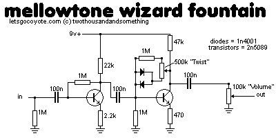
WWW.EATYOURGUITAR.COM <---- MY DIY STUFF
-
eatyourguitar
- IAMILFFAMOUS
- Posts: 3127
- Joined: Sun Oct 03, 2010 12:37 pm
- Location: USA, RI
Re: a really really big fuzz
![]() by crochambeau » Sun Mar 13, 2016 11:59 am
by crochambeau » Sun Mar 13, 2016 11:59 am
Nice find! I'll conduct the modification and get back to you.
I've got to get off my ass and bring to reality that what has been quoted through existence.
Rochambeau Musical Apparatus
Reverb storefront
Shark Tank
Rochambeau Musical Apparatus
Reverb storefront
Shark Tank
-
crochambeau
- IAMILF
- Posts: 2162
- Joined: Mon Jul 20, 2015 12:49 pm
- Location: Cascadia

Re: a really really big fuzz
![]() by eatyourguitar » Tue Mar 22, 2016 7:34 pm
by eatyourguitar » Tue Mar 22, 2016 7:34 pm

WWW.EATYOURGUITAR.COM <---- MY DIY STUFF
-
eatyourguitar
- IAMILFFAMOUS
- Posts: 3127
- Joined: Sun Oct 03, 2010 12:37 pm
- Location: USA, RI
Re: a really really big fuzz
![]() by crochambeau » Wed Mar 23, 2016 11:31 am
by crochambeau » Wed Mar 23, 2016 11:31 am
Sorry man, rough month for productivity my end, I will execute the modification and post results in the next day or so.
Just to confirm I understand what's happening here: I am to lift the center leg of SW2 and tie that to the Q3 side of R5?
Just to confirm I understand what's happening here: I am to lift the center leg of SW2 and tie that to the Q3 side of R5?
I've got to get off my ass and bring to reality that what has been quoted through existence.
Rochambeau Musical Apparatus
Reverb storefront
Shark Tank
Rochambeau Musical Apparatus
Reverb storefront
Shark Tank
-
crochambeau
- IAMILF
- Posts: 2162
- Joined: Mon Jul 20, 2015 12:49 pm
- Location: Cascadia
Re: a really really big fuzz
![]() by eatyourguitar » Wed Mar 23, 2016 1:53 pm
by eatyourguitar » Wed Mar 23, 2016 1:53 pm
EDIT: ignore this post
do not change the dirt mud switch!
the supply is labeled to the reverse polarity on the PCB. the transistors need to go in opposite the silkscreen. the dirt mud switch needs no modifications! do not cut any wires or move anything for the dirt mud switch please and thank you.
guys I really F*d up this PCB. sorry for the many hours of troubleshooting you put in at my mistake. 
do not change the dirt mud switch!
the supply is labeled to the reverse polarity on the PCB. the transistors need to go in opposite the silkscreen. the dirt mud switch needs no modifications! do not cut any wires or move anything for the dirt mud switch please and thank you.
guys I really F*d up this PCB. sorry for the many hours of troubleshooting you put in at my mistake.
Last edited by eatyourguitar on Wed Mar 23, 2016 2:34 pm, edited 1 time in total.
WWW.EATYOURGUITAR.COM <---- MY DIY STUFF
-
eatyourguitar
- IAMILFFAMOUS
- Posts: 3127
- Joined: Sun Oct 03, 2010 12:37 pm
- Location: USA, RI
Re: a really really big fuzz
![]() by eatyourguitar » Wed Mar 23, 2016 1:56 pm
by eatyourguitar » Wed Mar 23, 2016 1:56 pm
I would also suggest checking some other transistors in Q2 + Q3 since they might be damaged by now. check how it sounds, maybe damaged is good eh?
WWW.EATYOURGUITAR.COM <---- MY DIY STUFF
-
eatyourguitar
- IAMILFFAMOUS
- Posts: 3127
- Joined: Sun Oct 03, 2010 12:37 pm
- Location: USA, RI
Re: a really really big fuzz
![]() by eatyourguitar » Wed Mar 23, 2016 2:00 pm
by eatyourguitar » Wed Mar 23, 2016 2:00 pm
oh shit wait
WWW.EATYOURGUITAR.COM <---- MY DIY STUFF
-
eatyourguitar
- IAMILFFAMOUS
- Posts: 3127
- Joined: Sun Oct 03, 2010 12:37 pm
- Location: USA, RI
Re: a really really big fuzz
![]() by eatyourguitar » Wed Mar 23, 2016 2:16 pm
by eatyourguitar » Wed Mar 23, 2016 2:16 pm
this schematic is correct however the PCB does not match this schematic. the transistors must be installed opposite the silkscreen. the supply is labeled correct on the PCB. the center lug of PCB SW2 must not be connected on the PCB. the center lug of the actual switch connects to either side of R5. it makes very little difference where you put it. pick one or try both. maybe q3 collector would be best. that would give you two different EQ's (MUD + TONE knob) instead of the same thing twice with two different size caps.
Last edited by eatyourguitar on Wed Mar 23, 2016 2:21 pm, edited 1 time in total.
WWW.EATYOURGUITAR.COM <---- MY DIY STUFF
-
eatyourguitar
- IAMILFFAMOUS
- Posts: 3127
- Joined: Sun Oct 03, 2010 12:37 pm
- Location: USA, RI
Who is online
Users browsing this forum: No registered users and 4 guests
Sponsored Ad. (Please no inflated/repetitive clicking. Thanks!) 
|