
the PCB schematic is here
https://farm3.staticflickr.com/2942/15141087990_3b53abf726_o.gif
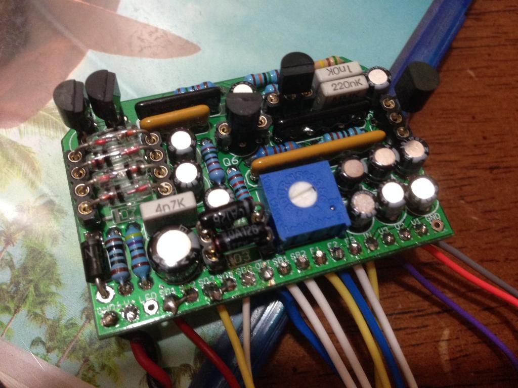
to anyone who purchased a kit. install wire jumprer or 0 Ohm resistor in D4 D6. install the germanium diodes in D5 D7. be very careful to not break the glass when bending the leads of the germanium diodes. do not install D2 D3. pads SD1 and SD2 get soldered together and then jumpered to SDG. optionally you can add a switch here to connect SDG to the SD1 SD2 group. SB1 and SB2 is the second footswitch on the ibanez standard fuzz. the trimmer is there to adjust the volume of the tone bypass footswitch. be careful not to install the 5 pin 10K bussed resistor array backwards. pin 1 is marked on the resistor array and on the PCB. the most common mistake that can go wrong with this build is electro static discharge damage to the FET as a result of improper handling. you should have your anti-static grounding strap on your wrist from the time you take the FET out of the bag to the time you put the back plate on the pedal. after it is soldered you do not need to worry so much as the resistors will mostly protect the FET. if you do not have an anti static ground strap you can google how to make one or just touch the metal on the back of your computer while you are seated getting ready to solder. here is a cheap wrist strap you can buy. it will save you hours of debugging dead FET's. you need to connect it to your computer chassis or something that you know for a fact has the metal chassis connected to the third prong on the wall outlet. if you have a broken extension cord you can use that to attach the wrist strap.
http://www.amazon.com/Belkin-Anti-Static-Wrist-Adjustable-Grounding/dp/B00004Z5D1
here is a little trick to get a ground
http://cdn.instructables.com/FG2/ORBR/H0OIWS2X/FG2ORBRH0OIWS2X.LARGE.jpg
I use something like this
http://www.digikey.com/product-detail/en/09838/16-1158-ND/3043259
DIY Ibanez Standard Fuzz?
Moderator: Ghost Hip
Forum rules
The DIY forum is for personal projects (things that are not for sale, not in production), info sharing, peer to peer assistance. No backdoor spamming (DIY posts that are actually advertisements for your business). No clones of in-production pedals. If you have concerns or questions, feel free to PM admin. Thanks so much!
The DIY forum is for personal projects (things that are not for sale, not in production), info sharing, peer to peer assistance. No backdoor spamming (DIY posts that are actually advertisements for your business). No clones of in-production pedals. If you have concerns or questions, feel free to PM admin. Thanks so much!
43 posts
• Page 3 of 3 • 1, 2, 3
Re: DIY Ibanez Standard Fuzz?
![]() by eatyourguitar » Mon Oct 27, 2014 7:14 pm
by eatyourguitar » Mon Oct 27, 2014 7:14 pm
WWW.EATYOURGUITAR.COM <---- MY DIY STUFF
-
eatyourguitar

- IAMILFFAMOUS

- Posts: 3127
- Joined: Sun Oct 03, 2010 12:37 pm
- Location: USA, RI
Re: DIY Ibanez Standard Fuzz?
![]() by eatyourguitar » Sun Nov 09, 2014 12:56 am
by eatyourguitar » Sun Nov 09, 2014 12:56 am
ATTENTION
2SC1815 TRANSISTORS PACKED WITH THE KITS WILL NOT WORK ON THIS PCB. YOU MUST USE 2N3904 OR SIMILAR TO FIT THE CBE HOLES. OR YOU CAN BEND THE LEGS ON THE 2SC1815 SO THAT THE BASE AND COLLECTOR ARE IN THE CORRECT HOLES. I WILL PROVIDE FREE 2N3904 TO ANYONE WHO PURCHASED A PCB OR KIT.
2SC1815 TRANSISTORS PACKED WITH THE KITS WILL NOT WORK ON THIS PCB. YOU MUST USE 2N3904 OR SIMILAR TO FIT THE CBE HOLES. OR YOU CAN BEND THE LEGS ON THE 2SC1815 SO THAT THE BASE AND COLLECTOR ARE IN THE CORRECT HOLES. I WILL PROVIDE FREE 2N3904 TO ANYONE WHO PURCHASED A PCB OR KIT.
WWW.EATYOURGUITAR.COM <---- MY DIY STUFF
-
eatyourguitar
- IAMILFFAMOUS
- Posts: 3127
- Joined: Sun Oct 03, 2010 12:37 pm
- Location: USA, RI
Re: DIY Ibanez Standard Fuzz?
![]() by Jighead » Sun Nov 09, 2014 1:20 am
by Jighead » Sun Nov 09, 2014 1:20 am
I figured this out (about the pinout) while probing for some signal the other night. I had some other BJT's to try out and they worked. 2SC1815 worked fine in Q3 though? Well, one of them worked in there, the other 3 were duds. I put in a clipping switch and jumpered the SD pads and that seems to be working well. I can't seem to get any octave up yet though, at least not much, even higher up the frets. Is the silk screen on Q4 and Q5 supposed to be like that? I thought the trannies would be facing each other, or away from each other depending on what trans. Either way it's a cool circuit, and I'm thoroughly enjoying it man. Thanks!
-
Jighead
- uncommitted

- Posts: 1
- Joined: Wed Oct 15, 2014 9:51 am
Re: DIY Ibanez Standard Fuzz?
![]() by eatyourguitar » Sun Nov 09, 2014 1:40 pm
by eatyourguitar » Sun Nov 09, 2014 1:40 pm
I can confirm %100 Q3 Q4 Q5 Q6 are all EBC. if you somehow got a 2SC1815 in there working it is an anomaly. I suggest switching back to 2N3904 to see if that fixes your octave problem. also, it has been mentioned on other forums that the differential pair (Q4 + Q5) should be matched for Hfe for best octave up in a superfuzz. I think it is unlikely that these vintage units had matched transistors and more unlikely that they stayed that way over 40 years of aging. then there is also the consideration that the emitters do not have matched resistors anyway so it kinda makes me wonder why people care about the matching. one of the emitters has a 10uf cap that will be all over the place above and below 1.5k depending on the frequency of the signal. you can also use a capacitor reactance calculator to find the frequency that the 10uf = 1.5k. use a carnegie chart to convert to a musical note on guitar to test your octave there.
Last edited by eatyourguitar on Thu Jul 21, 2016 8:05 am, edited 1 time in total.
WWW.EATYOURGUITAR.COM <---- MY DIY STUFF
-
eatyourguitar
- IAMILFFAMOUS
- Posts: 3127
- Joined: Sun Oct 03, 2010 12:37 pm
- Location: USA, RI
Re: DIY Ibanez Standard Fuzz?
![]() by frigid midget » Mon Nov 10, 2014 6:32 am
by frigid midget » Mon Nov 10, 2014 6:32 am
Can't wait to get started. Pointers that could prevent me from making silly noob mistakes are always welcome. It's been ages since my last diy pedal attempt, and I'm known for fucking up when it comes to grounding and wiring in general 
I won't be able to pick up my kit from the postal office untill wednesday. I'll report back with my build results when/if I manage to get it working.
So I'm safe to use the 2SC1815 transistors if I switch the C en B legs around, right? Or am I best of just ordering the right ones when I'm shopping for jacks/pots/enclosure?
-
frigid midget
- IAMILF

- Posts: 2503
- Joined: Mon Apr 21, 2014 6:31 pm
Re: DIY Ibanez Standard Fuzz?
![]() by eatyourguitar » Mon Nov 10, 2014 7:19 am
by eatyourguitar » Mon Nov 10, 2014 7:19 am
frigid midget wrote:Can't wait to get started. Pointers that could prevent me from making silly noob mistakes are always welcome. It's been ages since my last diy pedal attempt, and I'm known for fucking up when it comes to grounding and wiring in general
I won't be able to pick up my kit from the postal office untill wednesday. I'll report back with my build results when/if I manage to get it working.
So I'm safe to use the 2SC1815 transistors if I switch the C en B legs around, right? Or am I best of just ordering the right ones when I'm shopping for jacks/pots/enclosure?
I would use 2N3904 but you could just bend the c and b on the 2SC1815. it depends if you want an easy build or vintage correct. I can mail you some 2N3904 for free.
WWW.EATYOURGUITAR.COM <---- MY DIY STUFF
-
eatyourguitar
- IAMILFFAMOUS
- Posts: 3127
- Joined: Sun Oct 03, 2010 12:37 pm
- Location: USA, RI
Re: DIY Ibanez Standard Fuzz?
![]() by Ben79 » Sat Jan 10, 2015 7:45 pm
by Ben79 » Sat Jan 10, 2015 7:45 pm
to anyone who purchased a kit. install wire jumprer or 0 Ohm resistor in D4 D6. install the germanium diodes in D5 D7. be very careful to not break the glass when bending the leads of the germanium diodes. do not install D2 D3. pads SD1 and SD2 get soldered together and then jumpered to SDG. optionally you can add a switch here to connect SDG to the SD1 SD2 group. SB1 and SB2 is the second footswitch on the ibanez standard fuzz.
Bit confused by this.
The diodes are in the kit and there on the board so why shouldn't I install D2 and D3?
What's going on with D4 and D6?
-
Ben79

- experienced

- Posts: 510
- Joined: Thu Nov 01, 2012 6:16 pm
- Location: Germany
Re: DIY Ibanez Standard Fuzz?
![]() by ThurberMingus » Sun Jan 11, 2015 8:23 pm
by ThurberMingus » Sun Jan 11, 2015 8:23 pm
I've got a question regarding the JMK Standard Fuzz PCB. I would like to be able to have an LED for the tone footswitch, which is wired as an SPDT. Is there any way I can us a DPDT or 3PDT so I can have an indicator for the different settings?
neonblack wrote:SELL IT!
Don't form emotional bonds with metal boxes.
Live like me. Flip everything. Romanticize nothing. Accomplish nothing.
lost in music wrote:Digivolve into champions!
-
ThurberMingus

- FAMOUS

- Posts: 1474
- Joined: Tue Dec 31, 2013 12:04 pm
Re: DIY Ibanez Standard Fuzz?
![]() by Ben79 » Sun Jan 11, 2015 8:58 pm
by Ben79 » Sun Jan 11, 2015 8:58 pm
I'm pretty much still a beginner so I'm having a go at this for practice and waiting for someone to give me a mark out of 10. It might not be the best way to do it but I'm pretty sure this would work...
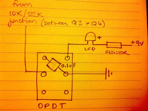
I'm using this schematic...
But it looks like the JMK switches the tone differently.
I'm using this schematic...
But it looks like the JMK switches the tone differently.
-
Ben79
- experienced
- Posts: 510
- Joined: Thu Nov 01, 2012 6:16 pm
- Location: Germany
Re: DIY Ibanez Standard Fuzz?
![]() by Ben79 » Sun Jan 11, 2015 9:22 pm
by Ben79 » Sun Jan 11, 2015 9:22 pm
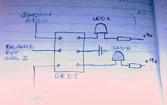
Using the schematic in the JMK http://jmkpcbs.com/wp-content/uploads/2014/03/Standard-Fuzz.pdf, I think this would be correct...
Actually, I had just presumed that bicoloured LEDs switch colour depending on voltage but I've just found out this is wrong so I lose marks there. It would still work though I think, if you remove one of the resistor sections, or probably better, sub the LED wiring from my previous attempt.
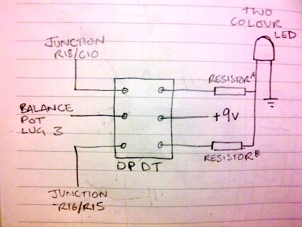
Actually, I had just presumed that bicoloured LEDs switch colour depending on voltage but I've just found out this is wrong so I lose marks there. It would still work though I think, if you remove one of the resistor sections, or probably better, sub the LED wiring from my previous attempt.
-
Ben79
- experienced
- Posts: 510
- Joined: Thu Nov 01, 2012 6:16 pm
- Location: Germany
Re: DIY Ibanez Standard Fuzz?
![]() by ThurberMingus » Mon Jan 12, 2015 1:58 am
by ThurberMingus » Mon Jan 12, 2015 1:58 am
I'm not so concerned with a bi-colored LED. In fact I think I'd like to use two separate LEDs so I could tell which setting it was on whether the pedal was on or off. Also on the JMK PCB there are three connection points for the switch already, so connecting with to the lug and junction won't be necessary.
neonblack wrote:SELL IT!
Don't form emotional bonds with metal boxes.
Live like me. Flip everything. Romanticize nothing. Accomplish nothing.
lost in music wrote:Digivolve into champions!
-
ThurberMingus
- FAMOUS
- Posts: 1474
- Joined: Tue Dec 31, 2013 12:04 pm
-
Ben79
- experienced
- Posts: 510
- Joined: Thu Nov 01, 2012 6:16 pm
- Location: Germany


43 posts
• Page 3 of 3 • 1, 2, 3
Who is online
Users browsing this forum: Google [Bot] and 4 guests
Sponsored Ad. (Please no inflated/repetitive clicking. Thanks!) 
|
